Chapter 10 PCI Controller
10-4
10.3 Detailed
Explanation
10.3.1 Terminology
Explanation
The following terms are used in this chapter.
•
Initiator
Means the bus Master of the PCI Bus. The TX4925 operates as the initiator when it obtains the
PCI Bus and issues PCI access.
•
Target
Means the bus Slave of the PCI Bus. The TX4925 operates as the target when an external PCI
device on the PCI Bus executes PCI access to the TX4925.
•
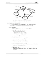
Host mode
One PCI Host device exists for one PCI Bus. The PCI Host device uses a PCI configuration
space to perform PCI configuration on other PCI devices on the PCI Bus.
The TX4925 is set to the Host mode if the ADDR[15] signal is High when the RESET* signal is
being deasserted.
•
Satellite mode
A PCI device other than the PCI Host device accepts configuration from the PCI Host device.
This state is referred to as the Satellite mode.
The TX4925 is set to the Satellite mode if the ADDR[15] signal is Low when the RESET*
signal is being deasserted.
•
DWORD, QWORD
DWORD expresses 32-bit words, and QWORD expresses 64-bit words. According to
conventions observed regarding MIPS architecture, this manual uses the following expressions:
Byte: 8-bit
Half-word: 16-bit
Word: 32-bit
Double-word: 64-bit
10.3.2 On-Chip
Register
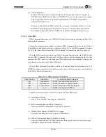
The PCI Controller on-chip register contains the PCI Configuration Space Register and the PCI
Controller Control Register. The registers that can be accessed vary according to whether the current
mode is the Host mode or the Satellite mode.
An external PCI Host device only accesses the PCI Configuration Space Register when in the
Satellite mode. This register is defined in the PCI Bus Specifications. A PCI configuration cycle is used
to access this register. This register cannot be accessed when in the Host mode. Section 10.5 “PCI
Configuration Space Register” explains each register in detail.
The PCI Controller Control Register is only accessed by the TX49 core and cannot be accessed from
the PCI Bus.
Содержание TMPR4925
Страница 1: ...64 Bit TX System RISC TX49 Family TMPR4925 Rev 3 0 ...
Страница 4: ......
Страница 15: ...Handling Precautions ...
Страница 16: ......
Страница 18: ...1 Using Toshiba Semiconductors Safely 1 2 ...
Страница 40: ...3 General Safety Precautions and Usage Considerations 3 18 ...
Страница 42: ...4 Precautions and Usage Considerations 4 2 ...
Страница 43: ...TMPR4925 ...
Страница 44: ......
Страница 54: ...Chapter 1 Features 1 8 ...
Страница 58: ...Chapter 2 Block Diagram 2 4 ...
Страница 88: ...Chapter 4 Address Mapping 4 12 ...
Страница 226: ...Chapter 8 DMA Controller 8 58 ...
Страница 260: ...Chapter 9 SDRAM Controller 9 34 ...
Страница 480: ...Chapter 15 Interrupt Controller 15 32 ...
Страница 554: ...Chapter 19 Real Time Clock RTC 19 8 ...
Страница 555: ...Chapter 20 Removed 20 1 20 Removed ...
Страница 556: ...Chapter 20 Removed 20 2 ...
Страница 564: ...Chapter 21 Extended EJTAG Interface 21 8 ...
Страница 580: ...Chapter 22 Electrical Characteristics 22 16 ...
Страница 586: ...Chapter 23 Pin Layout Package 23 6 23 2 Package Package Type Package Code 256 pin PBGA PBGA 4L P BGA256 2727 1 27A4 ...
Страница 588: ...Chapter 24 Usage Notes 24 2 ...
Страница 590: ...Appendix A TX49 H2 Core Supplement A 2 ...


