Chapter 11 Serial I/O Port
11-10
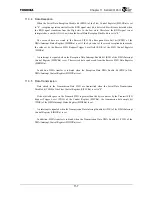
11.3.9 Reception
Time
Out
A Reception time out is detected and the Reception Time Out bit (TOUT) of the DMA/Interrupt
Status Register (SIDISR) is set under the following conditions.
•
Non-DMA transfer mode (SIDICRn.RDE = 0):
When at least 1 Byte of reception data exists in the Receive FIFO and the data reception time for
the 2 frames (2 Bytes) after the last reception has elapsed
•
DMA transfer mode (SIDICRn.RDE = 1):
When the data reception time for the 2 frames (2 Bytes) after the last reception has elapsed
regardless of whether reception data exists in the Receive FIFO
11.3.10 Software Reset
It is necessary to reset the FIFO and perform a software reset in the following situations.
(1) After transmission data is set in FIFO, etc., transmission started but stopped before its completion
(2) An overrun occurred during data reception
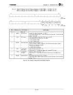
Software reset is performed by setting the Software Reset bit (SWRST) of the FIFO Control Register
(SIFCR). This bit automatically returns to “0” after initialization is complete. This bit must be set again
since all SIO registers are initialized by software resets.
Содержание TMPR4925
Страница 1: ...64 Bit TX System RISC TX49 Family TMPR4925 Rev 3 0 ...
Страница 4: ......
Страница 15: ...Handling Precautions ...
Страница 16: ......
Страница 18: ...1 Using Toshiba Semiconductors Safely 1 2 ...
Страница 40: ...3 General Safety Precautions and Usage Considerations 3 18 ...
Страница 42: ...4 Precautions and Usage Considerations 4 2 ...
Страница 43: ...TMPR4925 ...
Страница 44: ......
Страница 54: ...Chapter 1 Features 1 8 ...
Страница 58: ...Chapter 2 Block Diagram 2 4 ...
Страница 88: ...Chapter 4 Address Mapping 4 12 ...
Страница 226: ...Chapter 8 DMA Controller 8 58 ...
Страница 260: ...Chapter 9 SDRAM Controller 9 34 ...
Страница 480: ...Chapter 15 Interrupt Controller 15 32 ...
Страница 554: ...Chapter 19 Real Time Clock RTC 19 8 ...
Страница 555: ...Chapter 20 Removed 20 1 20 Removed ...
Страница 556: ...Chapter 20 Removed 20 2 ...
Страница 564: ...Chapter 21 Extended EJTAG Interface 21 8 ...
Страница 580: ...Chapter 22 Electrical Characteristics 22 16 ...
Страница 586: ...Chapter 23 Pin Layout Package 23 6 23 2 Package Package Type Package Code 256 pin PBGA PBGA 4L P BGA256 2727 1 27A4 ...
Страница 588: ...Chapter 24 Usage Notes 24 2 ...
Страница 590: ...Appendix A TX49 H2 Core Supplement A 2 ...

