Chapter 15 Interrupt Controller
15-5
15.3.2 Interrupt
Request
Detection
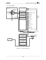
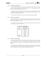
In order to perform interrupt detection, each register of the Interrupt Controller is initialized, then the
IDE bit of the Interrupt Detection Enable Register (IRDEN) is set to “1.” All interrupts detected by the
Interrupt Controller are masked when this bit is cleared.
It is possible to set each interrupt factor detection mode using Interrupt Detection Mode Register 0
(IRDM0) and Interrupt Detection Mode Register 1 (IRDM1). There are four detection modes: Low
level, High level, falling edge, and rising edge.
The detected interrupt factors can be read out from the Interrupt Pending Register (IRPND).
15.3.3 Interrupt
Level
Assigning
Interrupt levels from 0 to 7 are assigned to each detected interrupt using the Interrupt Level Register
(IRLVL0-7). Interrupt level 7 is the highest priority and interrupt level1 is the lowest priority. Level 0
interrupts will be masked. (Table 15.3.2).
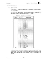
The priorities set by these interrupt levels will be given higher priority than the priorities provided
for each interrupt source indicated in Table 15.3.1.
Table 15.3.2 Interrupt Levels
Priority
Interrupt Level
(IRLVLn.ILm)
High 111
110
101
100
011
010
Low 001
Mask 000
15.3.4 Interrupt
Priority
Assigning
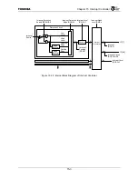
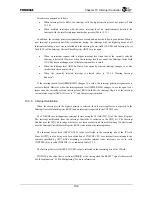
When multiple interrupt requests exist, the Interrupt Controller selects the interrupt with the highest
priority according to the priority level and interrupt number. Interrupt factors with an interrupt level
lower than the interrupt level specified by the Interrupt Mask Level Register (IRMSK) will be excluded
(masked).
When the interrupt with the highest priority is selected, then the interrupt number of that interrupt is
set in the interrupt factor field (CAUSE) of the Interrupt Current Status Register (IRCS), the interrupt
level is set in the Interrupt Level field (LVL), and the Interrupt Flag bit (IF) is set.
Содержание TMPR4925
Страница 1: ...64 Bit TX System RISC TX49 Family TMPR4925 Rev 3 0 ...
Страница 4: ......
Страница 15: ...Handling Precautions ...
Страница 16: ......
Страница 18: ...1 Using Toshiba Semiconductors Safely 1 2 ...
Страница 40: ...3 General Safety Precautions and Usage Considerations 3 18 ...
Страница 42: ...4 Precautions and Usage Considerations 4 2 ...
Страница 43: ...TMPR4925 ...
Страница 44: ......
Страница 54: ...Chapter 1 Features 1 8 ...
Страница 58: ...Chapter 2 Block Diagram 2 4 ...
Страница 88: ...Chapter 4 Address Mapping 4 12 ...
Страница 226: ...Chapter 8 DMA Controller 8 58 ...
Страница 260: ...Chapter 9 SDRAM Controller 9 34 ...
Страница 480: ...Chapter 15 Interrupt Controller 15 32 ...
Страница 554: ...Chapter 19 Real Time Clock RTC 19 8 ...
Страница 555: ...Chapter 20 Removed 20 1 20 Removed ...
Страница 556: ...Chapter 20 Removed 20 2 ...
Страница 564: ...Chapter 21 Extended EJTAG Interface 21 8 ...
Страница 580: ...Chapter 22 Electrical Characteristics 22 16 ...
Страница 586: ...Chapter 23 Pin Layout Package 23 6 23 2 Package Package Type Package Code 256 pin PBGA PBGA 4L P BGA256 2727 1 27A4 ...
Страница 588: ...Chapter 24 Usage Notes 24 2 ...
Страница 590: ...Appendix A TX49 H2 Core Supplement A 2 ...


