ZS3 Service Manual
Page 250 of 295
OLED Assembly (UI Assy)
–
Removal/Replacement
Required Parts
86901-00 ................... Assy, OLED2 Display Board
Overview of Procedure
9. Removal and re-installation of User Interface Assy
10. Replacement of OLED Display Board
11. System verification
Required Tools/Equipment
12. #1 Phillips Screwdriver
Procedure
UI Removal:
1.
Ens
ure the system is powered “OFF”.
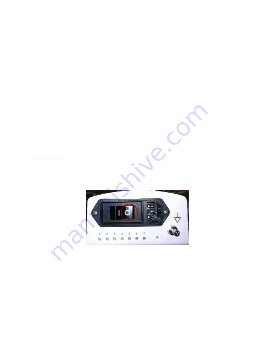
2.
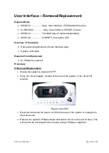
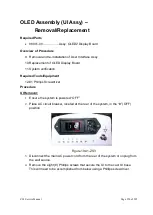
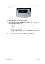
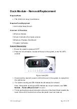
Place AC circuit breaker, located at the rear of the system, in the “
0
” (OFF)
position.
Figure 19.41-ZS3
3.
Disconnect the main AC power cord from the rear of the system or unplug from
the wall source.
4.
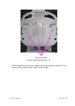
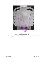
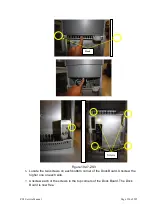
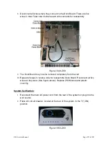
Remove the eight (8) Phillips screws that secure the UI to the cast UI base.
This will need to be accomplished from below using a Phillips screwdriver.
Summary of Contents for Zonare ZS3
Page 1: ...ZS3 Diagnostic Ultrasound System Service Manual ...
Page 120: ...ZS3 Service Manual Page 120 of 295 FTP Setup Enters Setup Network FTP ...
Page 124: ...ZS3 Service Manual Page 124 of 295 ...
Page 131: ...ZS3 Service Manual Page 131 of 295 13 System Diagrams ...
Page 132: ...ZS3 Service Manual Page 132 of 295 Power Block Diagram Figure 13 1 ZS3 Power Block Diagram ...
Page 133: ...ZS3 Service Manual Page 133 of 295 Cabling Diagram Figure 13 2 ZS3 Cabling Diagram ...
Page 138: ...ZS3 Service Manual Page 138 of 295 Figure 14 6 ZS3 ...
Page 185: ...ZS3 Service Manual Page 185 of 295 17 Preventative Maintenance Forms ...
Page 217: ...ZS3 Service Manual Page 217 of 295 Figure 18 8 ZS3 ...
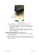
Page 252: ...ZS3 Service Manual Page 252 of 295 Figure 19 43 ZS3 Power Cable USB Cable ...
Page 295: ...P N 046 014026 00 2 0 ...

