ZS3 Service Manual
Page 253 of 295
OLED Display Board Removal/Replacement:
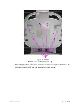
1. Ensure the User Interface is removed per steps 1 thru 5 of User Interface
Removal Procedure above.
2. Set the user interface (keys facing down) on a surface that will not damage the
surface of the User Interface.
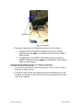
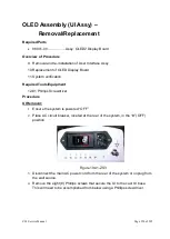
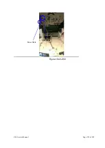
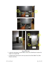
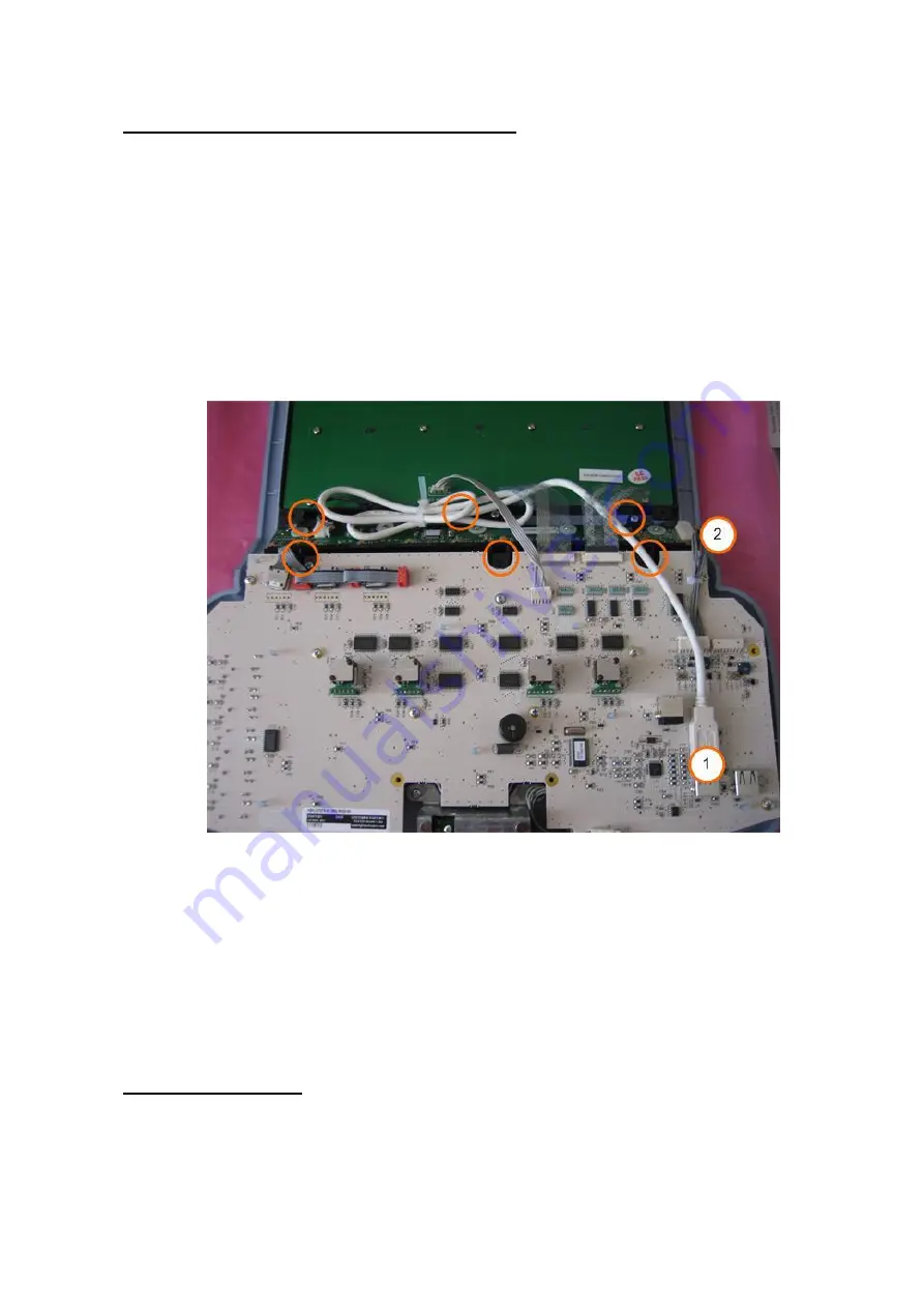
3. Disconnect the USB cable from the User Interface assembly (location 1, shown
below)
4. Disconnect the power cable from the OLED Display Board Assembly (location
2, shown below)
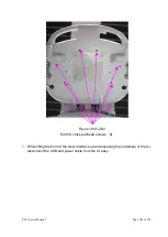
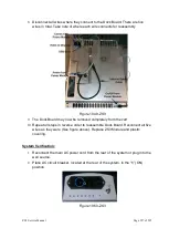
5. Remove the six (6) Phillips screws that retain the OLED assembly
Figure 19.44-ZS3
6. Slide the OLED Display Board Assembly out to the left (it is NOT necessary to
disconnect the two flex cables going to the QWERTY keyboard, as the OLED
assembly can be slid underneath for removal)
7. Reinstall OLED Display Board Assembly in the reverse order. Make sure to
connect both cables.
8. Reinstall the User Interface Assy, by executing the earlier steps in reverse
order, and proceed to System Verification.
System Verification:
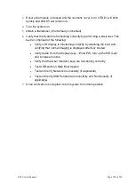
1.
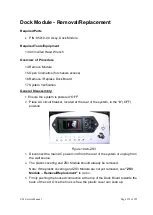
Reconnect the main AC power cord from the rear of the system or plug into the
wall source.
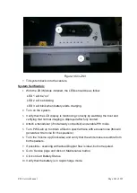
Summary of Contents for Zonare ZS3
Page 1: ...ZS3 Diagnostic Ultrasound System Service Manual ...
Page 120: ...ZS3 Service Manual Page 120 of 295 FTP Setup Enters Setup Network FTP ...
Page 124: ...ZS3 Service Manual Page 124 of 295 ...
Page 131: ...ZS3 Service Manual Page 131 of 295 13 System Diagrams ...
Page 132: ...ZS3 Service Manual Page 132 of 295 Power Block Diagram Figure 13 1 ZS3 Power Block Diagram ...
Page 133: ...ZS3 Service Manual Page 133 of 295 Cabling Diagram Figure 13 2 ZS3 Cabling Diagram ...
Page 138: ...ZS3 Service Manual Page 138 of 295 Figure 14 6 ZS3 ...
Page 185: ...ZS3 Service Manual Page 185 of 295 17 Preventative Maintenance Forms ...
Page 217: ...ZS3 Service Manual Page 217 of 295 Figure 18 8 ZS3 ...
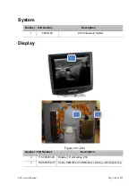
Page 252: ...ZS3 Service Manual Page 252 of 295 Figure 19 43 ZS3 Power Cable USB Cable ...
Page 295: ...P N 046 014026 00 2 0 ...

