ZS3 Service Manual
Page 247 of 295
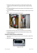
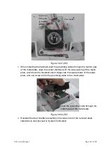
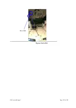
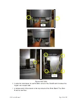
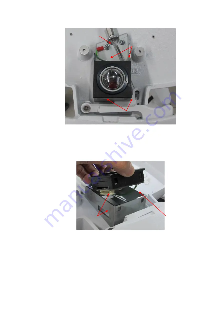
Figure 19.37-ZS3
3.
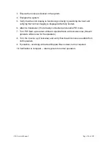
When installing the trackball, lead the grounding cables through the bottom gap
of the metal plate, align the socket interface with the side opening of the metal
plate, push down the trackball until it clasps into the square holes of the metal
plate, and use screws to fix the grounding cable to the metal plate.
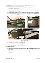
Figure 19.38-ZS3
4.
Reinstall the User Interface assembly in reverse order of the removal steps
listed above and proceed to System Verification.
Two hooks
Two hooks
Screw for
fixing the
grounding
cables
Align
Lead the grounding cable through the
bottom gap of the metal plate
Summary of Contents for Zonare ZS3
Page 1: ...ZS3 Diagnostic Ultrasound System Service Manual ...
Page 120: ...ZS3 Service Manual Page 120 of 295 FTP Setup Enters Setup Network FTP ...
Page 124: ...ZS3 Service Manual Page 124 of 295 ...
Page 131: ...ZS3 Service Manual Page 131 of 295 13 System Diagrams ...
Page 132: ...ZS3 Service Manual Page 132 of 295 Power Block Diagram Figure 13 1 ZS3 Power Block Diagram ...
Page 133: ...ZS3 Service Manual Page 133 of 295 Cabling Diagram Figure 13 2 ZS3 Cabling Diagram ...
Page 138: ...ZS3 Service Manual Page 138 of 295 Figure 14 6 ZS3 ...
Page 185: ...ZS3 Service Manual Page 185 of 295 17 Preventative Maintenance Forms ...
Page 217: ...ZS3 Service Manual Page 217 of 295 Figure 18 8 ZS3 ...
Page 252: ...ZS3 Service Manual Page 252 of 295 Figure 19 43 ZS3 Power Cable USB Cable ...
Page 295: ...P N 046 014026 00 2 0 ...

