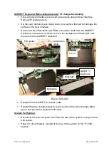
ZS3 Service Manual
Page 233 of 295
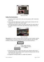
1. Reattach the display arm ground cable, and column ground cables to their
mounting point on the bottom of the upper support plate, using the retaining
screw.
2. R
econnect the Display’s power and video cables to the appropriate connectors
on the Dock Board.
3. Secure the connector/cable with tape to the chassis, to ensure it does not come
lose.
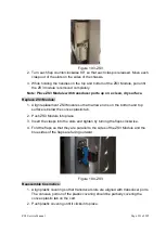
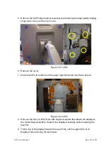
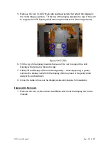
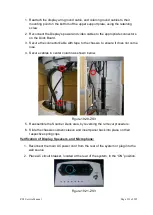
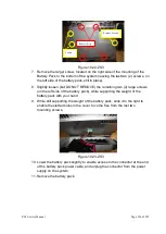
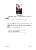
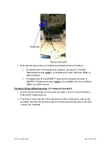
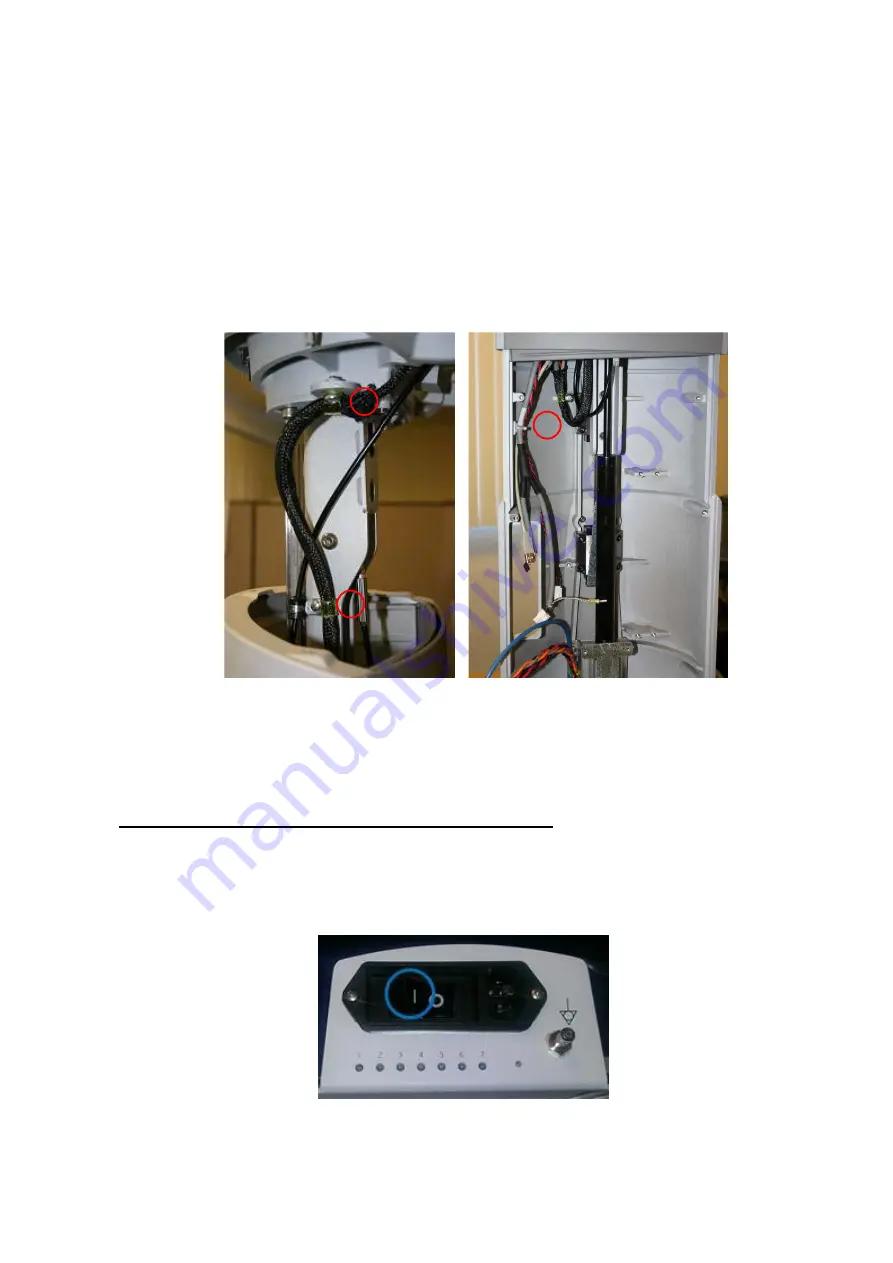
4. Secure cables in center column as shown below.
Figure 19.20-ZS3
5. Reassemble the Scanner Deck area, by reversing the removal procedure.
6. Slide the chassis cosmetic sleeve and insert panel back into place on their
respective spring clips.
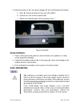
Verification of Display, Speakers, and Microphone:
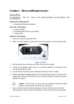
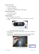
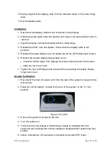
1. Reconnect the main AC power cord from the rear of the system or plug into the
wall source.
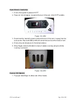
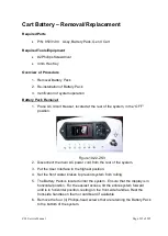
2. Place AC circuit breaker, located at the rear of the system
, in the “ON” position.
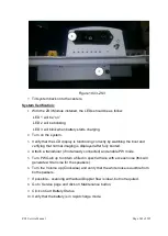
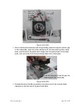
Figure 19.21-ZS3
Summary of Contents for Zonare ZS3
Page 1: ...ZS3 Diagnostic Ultrasound System Service Manual ...
Page 120: ...ZS3 Service Manual Page 120 of 295 FTP Setup Enters Setup Network FTP ...
Page 124: ...ZS3 Service Manual Page 124 of 295 ...
Page 131: ...ZS3 Service Manual Page 131 of 295 13 System Diagrams ...
Page 132: ...ZS3 Service Manual Page 132 of 295 Power Block Diagram Figure 13 1 ZS3 Power Block Diagram ...
Page 133: ...ZS3 Service Manual Page 133 of 295 Cabling Diagram Figure 13 2 ZS3 Cabling Diagram ...
Page 138: ...ZS3 Service Manual Page 138 of 295 Figure 14 6 ZS3 ...
Page 185: ...ZS3 Service Manual Page 185 of 295 17 Preventative Maintenance Forms ...
Page 217: ...ZS3 Service Manual Page 217 of 295 Figure 18 8 ZS3 ...
Page 252: ...ZS3 Service Manual Page 252 of 295 Figure 19 43 ZS3 Power Cable USB Cable ...
Page 295: ...P N 046 014026 00 2 0 ...

