ZS3 Service Manual
Page 143 of 295
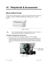
2. Power off the system.
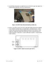
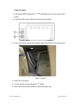
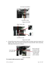
3. Attach the USB cable between the Sony UP-D25MD Color Printer and one of
the USB ports on the rear of the system
4. Connect the AC power cable to the rear panel power plug of the UP-D25MD
labeled “AC IN.”
5. Apply power to the system and printer.
6. Under the SETUP
ARCHIVE
->
DICOM
->
PRINTERS
page, create a new
“
Local/USB
” type printer entry for the Sony UP-25MD printer
7.
Enter in “
Sony UP-D25MD
” to the
Nick Name
field of the printer configuration
page
8. Enter in the desired printer settings, from those offered in the on-screen menu,
and then select “Save” to save.
9. Under the
ARCHIVE
->
STORE/PRINT
page, configure the “
”
button
for triggering a print to the Sony UP-25MD printer.
3. Connect a transducer to the system. Wait for startup to complete and image to
be shown.
4. Press the
“FREEZE”
key to capture an ultrasound image.
5. Verify a printed image is produced on the UP-D25
MD when the “
”
key
on the user interface is depressed.
NOTE:
Refer to the SONY UP-D25MD Installation Procedure (P/N S00119), or
Operator Manual from SONY, for detailed information on proper
operation of this device.
Summary of Contents for Zonare ZS3
Page 1: ...ZS3 Diagnostic Ultrasound System Service Manual ...
Page 120: ...ZS3 Service Manual Page 120 of 295 FTP Setup Enters Setup Network FTP ...
Page 124: ...ZS3 Service Manual Page 124 of 295 ...
Page 131: ...ZS3 Service Manual Page 131 of 295 13 System Diagrams ...
Page 132: ...ZS3 Service Manual Page 132 of 295 Power Block Diagram Figure 13 1 ZS3 Power Block Diagram ...
Page 133: ...ZS3 Service Manual Page 133 of 295 Cabling Diagram Figure 13 2 ZS3 Cabling Diagram ...
Page 138: ...ZS3 Service Manual Page 138 of 295 Figure 14 6 ZS3 ...
Page 185: ...ZS3 Service Manual Page 185 of 295 17 Preventative Maintenance Forms ...
Page 217: ...ZS3 Service Manual Page 217 of 295 Figure 18 8 ZS3 ...
Page 252: ...ZS3 Service Manual Page 252 of 295 Figure 19 43 ZS3 Power Cable USB Cable ...
Page 295: ...P N 046 014026 00 2 0 ...

