ZS3 Service Manual
Page 200 of 295
Sony or Mindray/Zonare Technical
Support
If the printer fails to print after these steps, contact Mindray/Zonare Tech Support.
TRANSDUCER PROBLEMS
Transducer not recognized by system (no B-mode imaging)
To ensure a positive connection, disconnect the transducer and reconnect it.
Inspect the metal contact pins on the transducer connector for any residue or
damage.
Inspect the scan module port for any residue or damage.
Insert the transducer into a different port on the system.
To determine a problem with the transducer or system, attach a different
transducer.
Disconnect the transducer. Power off the system. Power the system back on
and reattach the transducer to test for functionality.
If system still fails to operate any transducers, contact Mindray/Zonare Tech
Support.
IMAGING PROBLEMS
Poor B-mode image
Switch to a different transducer or probe port to see if the problem is with a
particular transducer or system port.
Ensure that there is an adequate supply of acoustic coupling gel and good
patient/transducer contact.
In the on-screen menu, under the Preset tab, select one of the factory default
settings (General, etc.) to determine possible maladjustment of user presets.
Adjust the various Doppler controls (gain, depth, frequency, etc.) to attempt to
resolve the problem.
Make sure the brightness and contrast settings of the LCD display have not been
altered from proper settings. For information about LCD display settings, see
LCD Display.
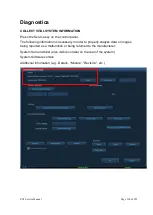
To ensure the quality of the gray scale resolution of the LCD display, use the
gray scale test pattern (via the Diagnostic menu) that is available. Ensure that all
shades can be visualized, making small adjustments to brightness and contrast
from factory defaults, as required, to see all intensities.
No/poor Color Mode image or PW Doppler
Make sure the “C” or “D” mode dial turns green upon activation.
Summary of Contents for Zonare ZS3
Page 1: ...ZS3 Diagnostic Ultrasound System Service Manual ...
Page 120: ...ZS3 Service Manual Page 120 of 295 FTP Setup Enters Setup Network FTP ...
Page 124: ...ZS3 Service Manual Page 124 of 295 ...
Page 131: ...ZS3 Service Manual Page 131 of 295 13 System Diagrams ...
Page 132: ...ZS3 Service Manual Page 132 of 295 Power Block Diagram Figure 13 1 ZS3 Power Block Diagram ...
Page 133: ...ZS3 Service Manual Page 133 of 295 Cabling Diagram Figure 13 2 ZS3 Cabling Diagram ...
Page 138: ...ZS3 Service Manual Page 138 of 295 Figure 14 6 ZS3 ...
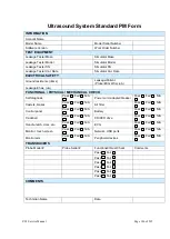
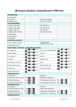
Page 185: ...ZS3 Service Manual Page 185 of 295 17 Preventative Maintenance Forms ...
Page 217: ...ZS3 Service Manual Page 217 of 295 Figure 18 8 ZS3 ...
Page 252: ...ZS3 Service Manual Page 252 of 295 Figure 19 43 ZS3 Power Cable USB Cable ...
Page 295: ...P N 046 014026 00 2 0 ...

