ZS3 Service Manual
Page 232 of 295
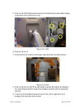
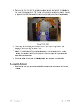
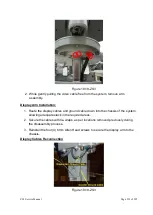
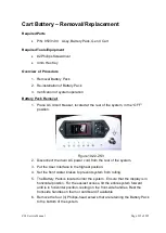
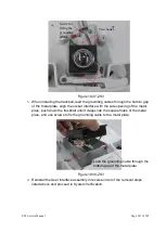
Figure 19.18-ZS3
2. While gently pulling the video cable free from the system, remove arm
assembly.
Display Arm Installation:
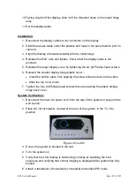
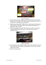
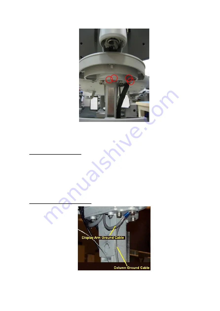
1. Route the display cables and ground cable down into the chassis of the system,
allowing adequate slack in the required areas.
2. Secure the cables with tie-wraps, as per locations removed previously during
the disassembly process.
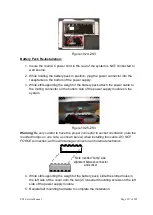
3. Reinstall the four (4) 6mm Allen Head screws to secure the display arm to the
chassis.
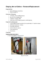
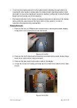
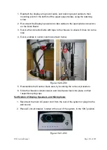
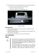
Display Cables Reconnection
Figure 19.19-ZS3
Summary of Contents for Zonare ZS3
Page 1: ...ZS3 Diagnostic Ultrasound System Service Manual ...
Page 120: ...ZS3 Service Manual Page 120 of 295 FTP Setup Enters Setup Network FTP ...
Page 124: ...ZS3 Service Manual Page 124 of 295 ...
Page 131: ...ZS3 Service Manual Page 131 of 295 13 System Diagrams ...
Page 132: ...ZS3 Service Manual Page 132 of 295 Power Block Diagram Figure 13 1 ZS3 Power Block Diagram ...
Page 133: ...ZS3 Service Manual Page 133 of 295 Cabling Diagram Figure 13 2 ZS3 Cabling Diagram ...
Page 138: ...ZS3 Service Manual Page 138 of 295 Figure 14 6 ZS3 ...
Page 185: ...ZS3 Service Manual Page 185 of 295 17 Preventative Maintenance Forms ...
Page 217: ...ZS3 Service Manual Page 217 of 295 Figure 18 8 ZS3 ...
Page 252: ...ZS3 Service Manual Page 252 of 295 Figure 19 43 ZS3 Power Cable USB Cable ...
Page 295: ...P N 046 014026 00 2 0 ...

