ZS3 Service Manual
Page 222 of 295
Verification of System:
1. Reconnect the main AC power cord from the rear of the cart or plug into the
wall source. Reconnection usb and RJ45 connections to back of cart.
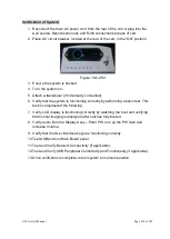
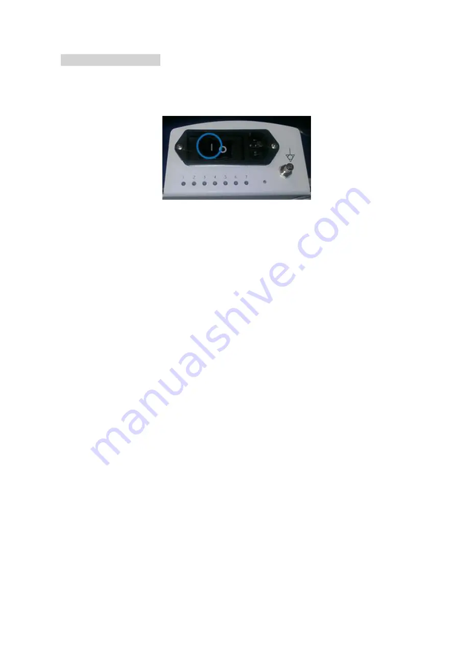
2. Place AC circuit breaker, located at the rear of the cart, in
the “ON” position.
Figure 19.5-ZS3
3. Ensure the system is docked.
4. Turn the system on
.
5. Attach a transducer (if not already connected)
6. Verify that the system is functioning correctly by performing a basic test. This
test is comprised of the following:
7. Verify LCD display is functioning correctly by watching the boot and verifying
that normal imaging is displayed after unit has fully booted.
8. Verify audio from the Display Assy
– Enter PW, turn up the PW Gain and
increase Volume.
9. Verify that the User Interface keys are functioning correctly.
10. Test USB ports on Main Board panel.
11. Test and Verify Network Connectivity (if applicable).
12. Test and Verify USB Peripheral Connectivity and Functionality (if applicable).
13. Once verification is complete, return system to normal operation.
Summary of Contents for Zonare ZS3
Page 1: ...ZS3 Diagnostic Ultrasound System Service Manual ...
Page 120: ...ZS3 Service Manual Page 120 of 295 FTP Setup Enters Setup Network FTP ...
Page 124: ...ZS3 Service Manual Page 124 of 295 ...
Page 131: ...ZS3 Service Manual Page 131 of 295 13 System Diagrams ...
Page 132: ...ZS3 Service Manual Page 132 of 295 Power Block Diagram Figure 13 1 ZS3 Power Block Diagram ...
Page 133: ...ZS3 Service Manual Page 133 of 295 Cabling Diagram Figure 13 2 ZS3 Cabling Diagram ...
Page 138: ...ZS3 Service Manual Page 138 of 295 Figure 14 6 ZS3 ...
Page 185: ...ZS3 Service Manual Page 185 of 295 17 Preventative Maintenance Forms ...
Page 217: ...ZS3 Service Manual Page 217 of 295 Figure 18 8 ZS3 ...
Page 252: ...ZS3 Service Manual Page 252 of 295 Figure 19 43 ZS3 Power Cable USB Cable ...
Page 295: ...P N 046 014026 00 2 0 ...

