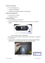
ZS3 Service Manual
Page 231 of 295
5.
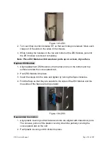
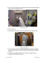
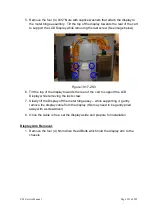
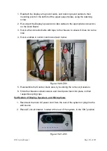
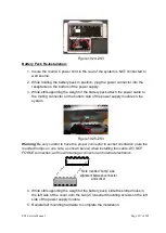
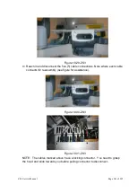
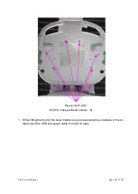
Remove the four (4) 9/32” Nuts with captive washers that attach the display to
the metal hinge assembly. Tilt the top of the display towards the rear of the cart
to support the LCD Display while removing the last screw (See image below).
Figure 19.17-ZS3
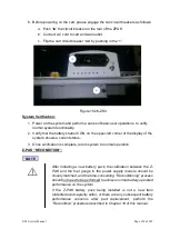
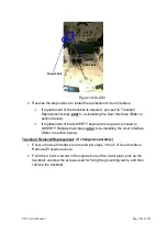
6. Tilt the top of the display towards the rear of the cart to support the LCD
Display while removing the last screw.
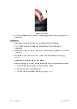
7. Slowly lift the Display off the metal hinge assy
– while supporting it, gently
remove the display cable from the display (this may need to be gently pried
away with a screwdriver)
8. Once the cable is free, set the display aside and prepare for installation
Display Arm Removal:
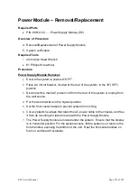
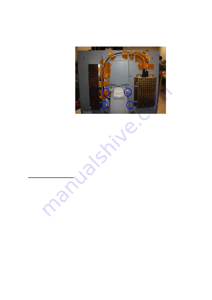
1. Remove the four (4) 6mm Allen Head Bolts which hold the display arm to the
chassis.
Summary of Contents for Zonare ZS3
Page 1: ...ZS3 Diagnostic Ultrasound System Service Manual ...
Page 120: ...ZS3 Service Manual Page 120 of 295 FTP Setup Enters Setup Network FTP ...
Page 124: ...ZS3 Service Manual Page 124 of 295 ...
Page 131: ...ZS3 Service Manual Page 131 of 295 13 System Diagrams ...
Page 132: ...ZS3 Service Manual Page 132 of 295 Power Block Diagram Figure 13 1 ZS3 Power Block Diagram ...
Page 133: ...ZS3 Service Manual Page 133 of 295 Cabling Diagram Figure 13 2 ZS3 Cabling Diagram ...
Page 138: ...ZS3 Service Manual Page 138 of 295 Figure 14 6 ZS3 ...
Page 185: ...ZS3 Service Manual Page 185 of 295 17 Preventative Maintenance Forms ...
Page 217: ...ZS3 Service Manual Page 217 of 295 Figure 18 8 ZS3 ...
Page 252: ...ZS3 Service Manual Page 252 of 295 Figure 19 43 ZS3 Power Cable USB Cable ...
Page 295: ...P N 046 014026 00 2 0 ...

