


98
Operating Data Area
Section 4-6
Note
(1) In memory operation, the operation of the Position Completion Flag de-
pends on the completion code set for memory operation. For details, refer
to
SECTION 8 Memory Operation
.
(2) The bit for X-axis is also used as “Unit in Initial Processing”.
(3) During memory operation, PCU status is input for the axis that started op-
eration or the actual moving axis/axes specified by the axis designation.
For details on which axis/axes status is input, refer to
8-1-2 Axis Desig-
nation and Flags
.
4-6
Operating Data Area
The operating data area is used for setting the data for operating commands
output to the PCU.
When an operating command is output to the PCU from the operating mem-
ory area, the PCU executes the command based on the settings in the operat-
ing data area.
4-6-1
Outline
CPU Unit memory (in the DM Area or EM Area) is allocated as the operating
data area according to the common parameter settings. (Refer to
4-3 Com-
mon Parameter Area
.) The beginning word of the operating data area is deter-
mined in the way shown below.
DM Area Words Allocated to Special I/O Units
If 0000 (DM Area words allocated to Special I/O Units) is set for the common
parameter used for the operating data area designation (word m), the begin-
ning word, l, of the operating data area will be as follows:
• NC1
@
3: l = m + 32 = 100
×
unit 32
• NC2
@
3: l = m + 60 = 100
×
unit 60
• NC4
@
3: l = m + 116 = 100
×
unit 116
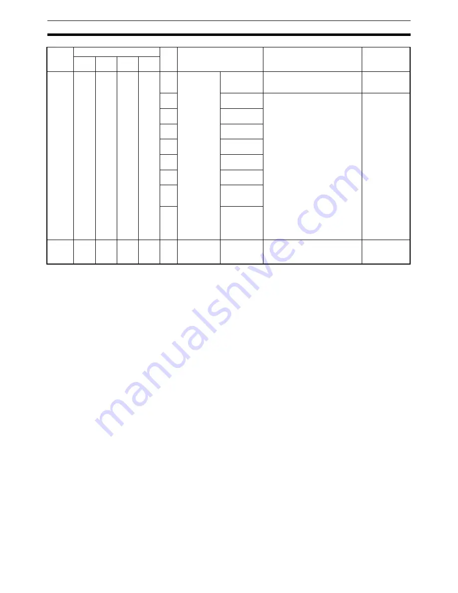
NC4
@
3
NC2
@
3
NC1
@
3
n+9
n+5
n+3
n+12
n+8
n+15
n+18
00
to
07
External I/O
status
Not used
---
---
08
CW limit input
signal
Reflect the status of the input and
output signals for the axes.
1: Signal enabled
0: Signal disabled
Note
Here, “enabled” and “dis-
abled” are not the same as
electrical ON and OFF. For
details, refer to
4-4 Axis
Parameter Area
.
---
09
CCW limit
input signal
10
Origin proxim-
ity input signal
11
Origin input
signal
12
Interrupt input
signal
13
Emergency
input signal
14
Positioning
completed
input signal
15
Error counter
reset output/
origin-adjust-
ment com-
mand output
NC4
@
3
NC2
@
3
NC1
@
3
n+10
n+6
n+4
n+13
n+9
n+16
n+19
00
to
15
Error code
Error code
(see note 3)
Indicates the error code when an
error occurs.
SECTION 11
Troubleshooting
Model
Words
Bits
Name
Operation
Reference
X
axis
Y
axis
Z axis
U
axis
Содержание CJ1W-C113 - REV 02-2008
Страница 1: ...Position Control Units Cat No W397 E1 07 SYSMAC CJ1W NC113 213 413 133 233 433 OPERATION MANUAL ...
Страница 2: ...CJ1W NC113 213 413 133 233 433 Position Control Units Operation Manual Revised February 2008 ...
Страница 3: ...iv ...
Страница 13: ...xiv ...
Страница 15: ...xvi ...
Страница 19: ...xx ...
Страница 27: ...xxviii Conformance to EC Directives 6 ...
Страница 43: ...16 Control System Principles Section 1 7 ...
Страница 47: ...20 Basic Procedures Section 2 ...
Страница 139: ...112 Examples of Parameter Settings Section 4 9 ...
Страница 173: ...146 Transferring Data with CX Position Section 5 7 ...
Страница 223: ...196 Sample Program Section 7 7 ...
Страница 259: ...232 Sample Program Section 8 10 ...
Страница 293: ...266 Easy Backup Function Ver 2 0 or later Section 9 11 ...
Страница 369: ...342 Reading Error Information with CX Position Section 11 8 ...
Страница 385: ...358 Common Parameter Area Appendix C ...
Страница 399: ...372 Parameter Coding Sheets Appendix E ...


