


355
Estimating Times and Pulses for Acceleration/Deceleration
Appendix B
The following is an explanation of the deceleration time when changing speed settings during positioning with
the acceleration/deceleration time designation parameter set to 1.
Deceleration Time Calculation for Speed Changes During Positioning
If the acceleration/deceleration time designation parameter (DM m+19 for the X axis) is set so that acceleration
and deceleration times are directly specified as the times required to go from the present speed to the target
speed, the specified times are used for the time required to reach the target speed and the positioning time
from the present speed to the time that positioning is finished. Under the following conditions, however, the
specified deceleration time will not be used and instead deceleration to 0 pps will begin immediately.
This will occur when all of the following 4 conditions are met at the same time.
1.
The acceleration/deceleration time designation parameter is set to directly specify the time required to go
from the present speed to the target speed.
2.
The speed is changed during positioning.
3.
The target speed is less than half of the present speed.
4.
The speed is changed at a position that exceeds the deceleration starting limit position, which is calculated
from the target speed and deceleration speed in step 3.
Therefore, you must consider the final deceleration rate from the target speed at the completion of positioning
and determine if positioning is possible for the specified deceleration.
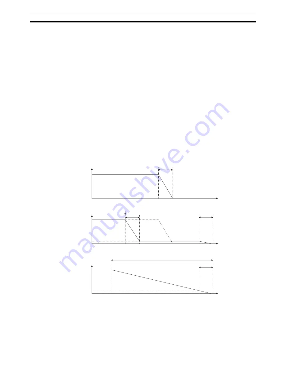
Consider the following example.
Figure 1
shows a graph of positioning to a final target position of 216,000
pulses. If the speed is changed to 400 pps at near 193,000 pulses, the positioning operation will be as shown
in
Figure 3,
and not as shown in
Figure 2.
When changing the speed during positioning, the time required for the Position Control Unit to stop from the
target speed (400 pps) is the set deceleration time of 500 ms. The following equation is used to calculate the
deceleration starting limit position (see
Figure 3
).
The deceleration starting limit position is the position where the speed must be changed to prevent exceeding
the target position. If an attempt is made to change the speed past this point, the specified speed will not be
achieved and the axis will decelerate to a stop.
Speed (pps)
Time (ms)
Speed (pps)
Time (ms)
Speed (pps)
Time (ms)
500
500
10,000
500
12,500
500
Figure 1:
Normal operation
Figure 2:
Figure 3:
10,000
400
10,000
400
When there is no
speed change,
positioning will stop
at the target position
in the specified
deceleration time.
The Unit may
behave as shown in
figure 3 and not as
shown in figure 2.
The calculation of the
deceleration starting
limit position for the
Unit.
Содержание CJ1W-C113 - REV 02-2008
Страница 1: ...Position Control Units Cat No W397 E1 07 SYSMAC CJ1W NC113 213 413 133 233 433 OPERATION MANUAL ...
Страница 2: ...CJ1W NC113 213 413 133 233 433 Position Control Units Operation Manual Revised February 2008 ...
Страница 3: ...iv ...
Страница 13: ...xiv ...
Страница 15: ...xvi ...
Страница 19: ...xx ...
Страница 27: ...xxviii Conformance to EC Directives 6 ...
Страница 43: ...16 Control System Principles Section 1 7 ...
Страница 47: ...20 Basic Procedures Section 2 ...
Страница 139: ...112 Examples of Parameter Settings Section 4 9 ...
Страница 173: ...146 Transferring Data with CX Position Section 5 7 ...
Страница 223: ...196 Sample Program Section 7 7 ...
Страница 259: ...232 Sample Program Section 8 10 ...
Страница 293: ...266 Easy Backup Function Ver 2 0 or later Section 9 11 ...
Страница 369: ...342 Reading Error Information with CX Position Section 11 8 ...
Страница 385: ...358 Common Parameter Area Appendix C ...
Страница 399: ...372 Parameter Coding Sheets Appendix E ...


