MAX32600 User’s Guide
System Clock, Timers/Counters, Watchdog Timers and Real Time Clock
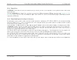
10.1 System Clock
Control of the ADC Clock Source Configuration
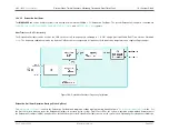
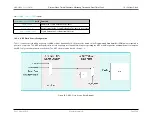
Clock configuration involves a trade-off with power and performance. The lowest jitter 8MHz clock with the best duty cycle provides the smallest degradation from
aperture jitter. For lower ADC sample rates and lower frequency analog inputs this may be less of a consideration.The best performance is achieved with an external
8MHz crystal. The lowest power is achieved using the internal 24MHz Relaxation oscillator.
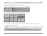
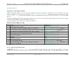
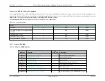
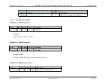
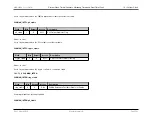
The following table illustrates the register controls for common ADC clock configurations.
ADC Clock Configuration Table
Mode
CLKMAN_CLK_CTRL.adc_source_select
Disabled
0
00b
000b
PLL 8MHz Output (PLL configured and
enabled)
1
00b
000b
8MHz External Crystal
1
01b
000b
24MHz External Crystal
1
10b
010b
24MHz Relaxation Oscillator
1
11b
010b
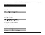
10.1.5
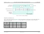
Registers (CLKMAN)
10.1.5.1
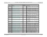
Module CLKMAN Registers
Address
Register
32b
Word Len
Description
0x40090400
1
System Clock Configuration
0x40090404
1
System Clock Controls
0x40090408
1
Interrupt Flags
0x4009040C
1
Interrupt Enable/Disable Controls
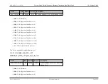
0x40090410
1
Trim Calculation Controls
0x40090424
1
I2C Timer Control
0x40090440
1
Control Settings for CLK0 - System Clock
0x40090444
1
Control Settings for CLK1 - GPIO Module Clock
Rev.1.3 April 2015
Maxim Integrated
Page 510
Содержание MAX32600
Страница 1: ...MAX32600 User s Guide April 2015...

