MAX32600 User’s Guide
Communication Peripherals
7.1 I²C
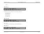
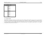
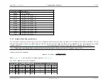
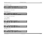
i2cm_clk_scale
Description
0000b
CLK is Disabled
0001b
(System Clock Source / 1)
0010b
(System Clock Source / 2)
0011b
(System Clock Source / 4)
0100b
(System Clock Source / 8)
0101b
(System Clock Source / 16)
0110b
(System Clock Source / 32)
0111b
(System Clock Source / 64)
1000b
(System Clock Source / 128)
1001b
(System Clock Source / 256)
other
(System Clock Source / 1)
7.1.6.1
Peripheral Clock Frequency Selection
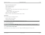
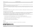
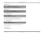
To set up the SCL frequency, it is necessary to set up four configuration registers to achieve proper operation: the I
2
C Peripheral Clock, Filter Clock Divisor, SCL low
time, and SCL high time. The amount of time required for the SCL low time versus SCL high time (Duty Cycle) is dependent on the specific slave device(s) being
communicated with.
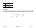
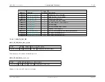
SCL Clock Configuration Common Calculations
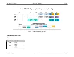
shows typical target SCL low versus SLC high times for standard slave I
2
C devices.
Note
Pullup delays, input filtering delays, and multi-master clock synchronization affect the observed SCL frequency on the I
2
C bus.
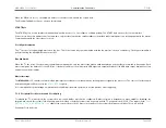
Full-Speed Target SCL Calculation
Target SCL Frequency
=
Peripheral Clock
f s
_
f ilter
_
clk
_
div
Where
is an 8-bit number to divide down the
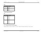
SCL Clock Configuration Common Calculations
PCLK
F
I2C
I²C
DUTY
F
HOLD
T
RC
Filt CLK Divisor
SCL Hi
SCL Lo
24
100
0.67
1
1000
12
38
144
24
400
0.67
0.25
300
3
5
36
12
100
0.67
1
1000
6
17
72
12
400
0.67
0.25
300
2
1
18
6
100
0.67
1
1000
3
7
36
Rev.1.3 April 2015
Maxim Integrated
Page 227
Содержание MAX32600
Страница 1: ...MAX32600 User s Guide April 2015...

