MAX32600 User’s Guide
Pin Configurations, Packages, and Special Function Multiplexing
5.4 GPIO Pins and Peripheral Mode Functions
GPIO Function
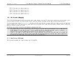
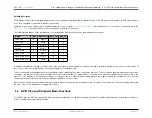
All eight GPIO pins in each GPIO port have access to a common set of low-level peripheral functions that can use GPIO pins as inputs or outputs:
• Output signal streams from Pulse Trains 0 through 7 (three options for each pin)
• Input/output signals (depending on configured timer mode) for the 32-bit Timer (0, 1, 2, and 3) modules
Note
The following tables apply to both Compact and Standard Pin Layouts; however, only P0, P1, and P2 are available for the Compact Pin Layout.
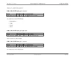
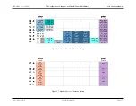
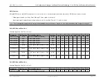
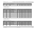
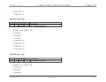
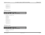
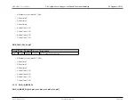
Px.0 GPIO Pins and Functions
Function Support by Port (Px.0, x=0 to 7)
Peripheral
Pin Function
Function Description
Direction
P0.0
P1.0
P2.0
P3.0
P4.0
P5.0
P6.0
P7.0
GPIO Port Pin
Px.0
Port Pin (Firmware Controlled)
In/Out
X
X
X
X
X
X
X
X
Pulse Train 0
PT0
Pulse Train 0 Output
Out
X
X
X
X
X
Pulse Train 0
PT0
Pulse Train 0 Output
Out
X
X
X
X
X
Pulse Train 4
PT4
Pulse Train 4 Output
Out
X
X
X
X
X
32-bit Timer 0
TMR0
32-bit Timer/Counter 0 Input or Out-
put
In/Out
X
X
X
X
X
32-bit Timer 1
TMR1
32-bit Timer/Counter 1 Input or Out-
put
In/Out
X
X
X
X
X
32-bit Timer 2
TMR2
32-bit Timer/Counter 2 Input or Out-
put
In/Out
X
X
X
X
X
32-bit Timer 3
TMR3
32-bit Timer/Counter 3 Input or Out-
put
In/Out
X
X
X
X
X
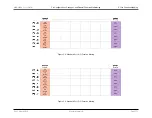
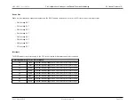
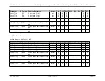
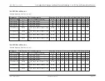
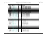
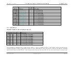
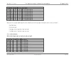
Px.1 GPIO Pins and Functions
Function Support by Port (Px.1, x=0 to 7)
Peripheral
Pin Function
Function Description
Direction
P0.1
P1.1
P2.1
P3.1
P4.1
P5.1
P6.1
P7.1
GPIO Port Pin
Px.1
Port Pin (Firmware Controlled)
In/Out
X
X
X
X
X
X
X
X
Rev.1.3 April 2015
Maxim Integrated
Page 176
Содержание MAX32600
Страница 1: ...MAX32600 User s Guide April 2015...


