


MAX32600 User’s Guide
Communication Peripherals
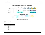
7.1 I²C
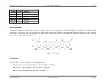
Bit Transfer
Both SDA and SCL lines are bi-directional lines connected to a positive supply voltage via a current source or a pullup resistor. When the bus is free, the lines are in
high state. The data on the SDA line must be stable when the SCL line is high.
Communication starts when the SDA line switches from high to low state and the SCL line is high. Communication stops when the SDA line switches from low to high
state and the SCL line is high. Only the master generates the start and stop conditions. After the start condition and during communication, the bus is considered
busy.
Start and Stop Conditions
A high to low transition on the SDA line while SCL is high defines a start condition; a low to high transition on the SDA line while SCL is high defines a stop condition.
Acknowledge (ACK) and Not Acknowledge (NACK)
The acknowledge takes place after every byte after which the receiver signals the transmitter that the byte was successfully received and another byte may be sent.
The acknowledge signal operates as follows: the transmitter releases the SDA line during the acknowledge clock pulse so the receiver can pull the SDA line to the
low state (it remains stable in the low state during the high period of this clock pulse on the SCL line). Setup and hold times may affect this behavior.
A NACK signal will occur when the SDA remains high during this ninth clock pulse. The I
2
C master can then generate either a stop condition to abort the transfer or
a repeated start condition to start a new transfer. There are five conditions that lead to NACK signal generation:
1. No receiver is present on the bus with the transmitted address so there is no device to respond with an acknowledge signal.
2. The receiver is unable to receive or transmit because it is performing some real-time function and is not ready to start communication with the master.
3. During the transfer, the receiver gets data or commands that it does not understand.
4. During the transfer, the receiver cannot receive any more data bytes.
5. A master-receiver must signal the end of the transfer to the slave transmitter.
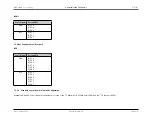
Addressing
This block can run in master or slave mode, and in fast or standard mode. The first byte sent defines the type of addressing.
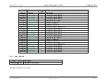
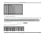
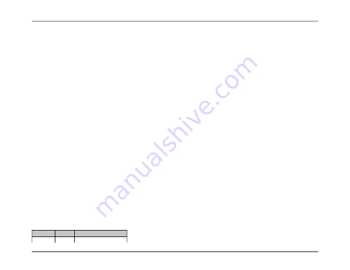
Definition of the First Byte
7-1 bits
R/W bit
Definition
0000 000
0
General Call Address
Rev.1.3 April 2015
Maxim Integrated
Page 224
Содержание MAX32600
Страница 1: ...MAX32600 User s Guide April 2015...


