MAX32600 User’s Guide
LCD Controller
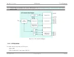
13.3 LCD Configuration
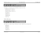
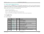
• 10b: 1/3 duty (1/3 bias, 3X segment mux)
• 11b: 1/4 duty (1/3 bias, 4X segment mux)
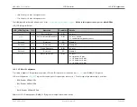
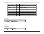
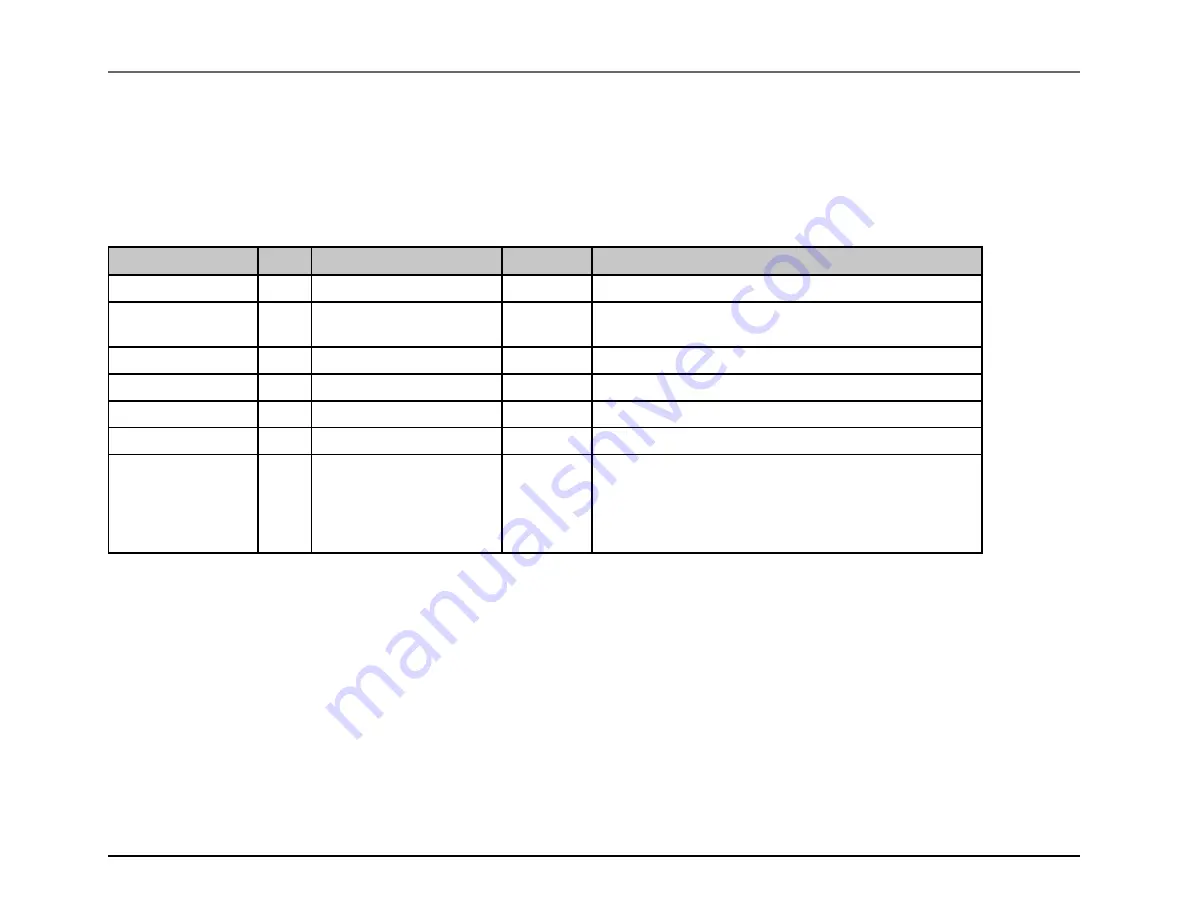
The following table outlines the bit addresses for the
LCD Internal Register Adjust registers
Writes to this register can only occur when OPM=0
.
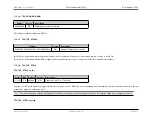
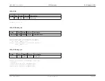
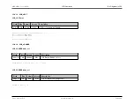
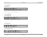
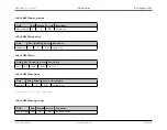
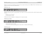
LCD_LCRA Register Details
LCD_LCRA Register
Bit
Operation
Read/Write
Details
3:0
Resistor Adjust
R/W
0 = reset
4
Resistor Internally Grounded
R/W
0 = reset/ disable;
1 = enable internal ground connect
Reserved
5
Reserved
RO
Always 0
Reserved
7:6
Reserved
R/W
Always 00
12:8
Frame Frequency
R/W
0 = reset
Reserved
13
Reserved
RO
Always 0
15:14
Duty Cycle Select
R/W
0 = reset;
0 = static with 1/2 bias;
1 = 1/2 duty with 1/2 bias;
2 = 1/3 duty with 1/3 bias;
3 = 1/4 duty with 1/3 bias
13.3.5
LCD Port Configuration
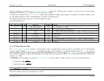
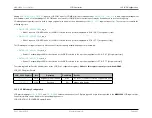
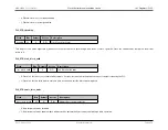
To properly configure LCD segment pin operation, LCD and I/O registers must be written via
and IOMAN_LCD registers.
LCD port configuration
register bits enable pairs of segment pins when set to 1. The bit/segment pin relationship is as follows:
• Bit 0: Enables SEG0+SEG1
• Bit 1: Enables SEG2+SEG3
• . . .
• Bit 19: Enables SEG38+SEG39
Within the LCD I/O management (IOMAN_LCD) registers, multiple fields must be written.
Rev.1.3 April 2015
Maxim Integrated
Page 640
Содержание MAX32600
Страница 1: ...MAX32600 User s Guide April 2015...


