


MAX32600 User’s Guide
Communication Peripherals
7.2 SPI
7.2.2
SPI Port and Pin Configurations
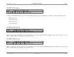
SPI Wiring Configurations
•
3-Wire SPI
: SS, SCK, SDIO
•
4-Wire SPI
: SS, SCK, MOSI, MISO
•
Dual SPI
: SS, SCK, SDIO0, SDIO1
•
Quad SPI
: SS, SCK, SDIO0, SDIO1, SDIO2, SDIO3
Slave Ready (SR) lines are optional; configuration details can be found in the
section.
Note
See
for a detailed mapping of
MAX32600
multiplexed function locations. Functional priority distinction is included in the mapping.
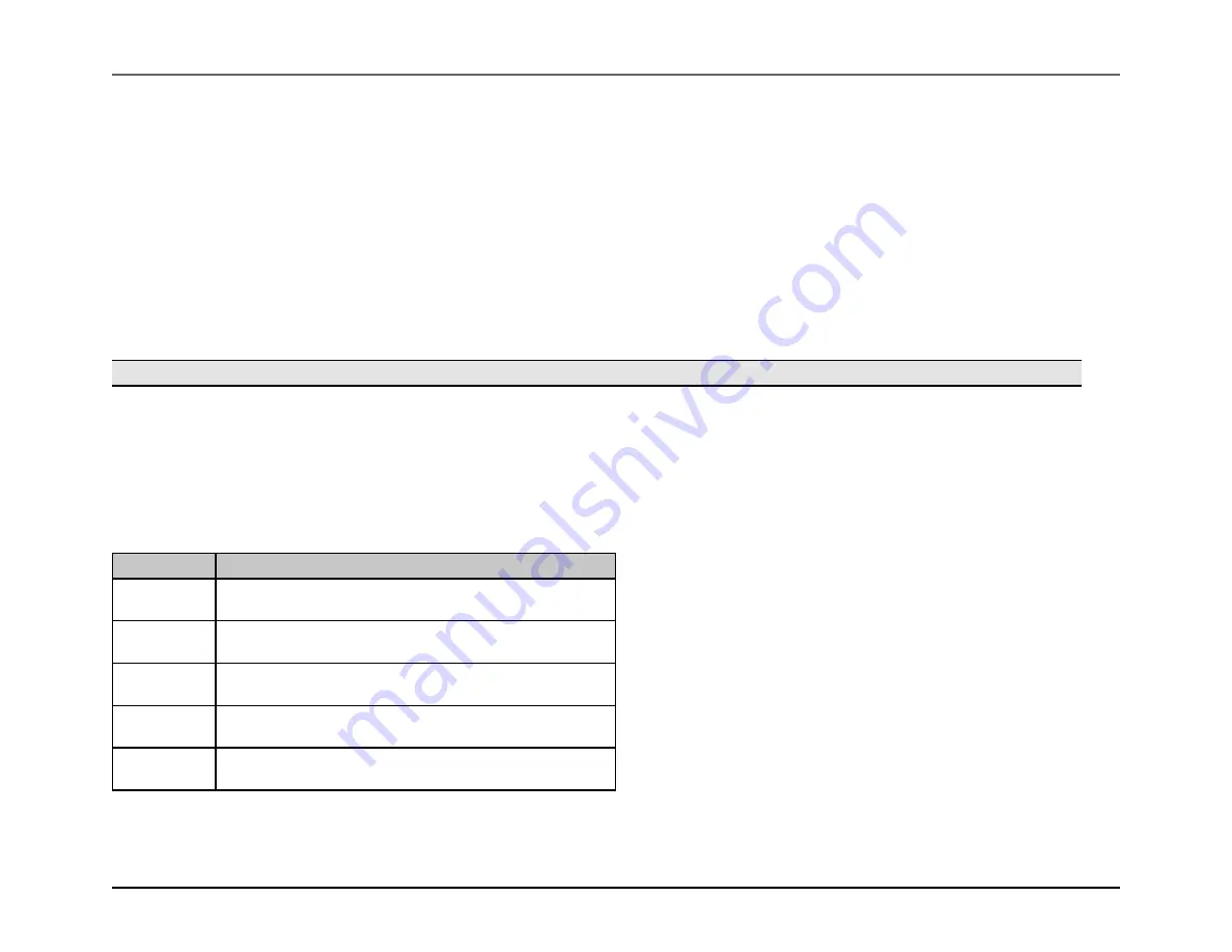
7.2.2.1
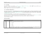
Compact Layout (7mm x 7mm) Configuration
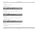
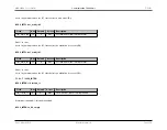
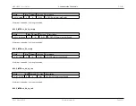
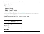
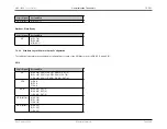
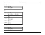
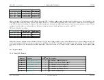
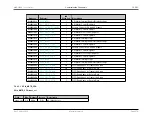
The tables below contain the available pin configurations for each of the SPI Master ports (SPI0, SPI1, and SPI2).
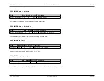
SPI0
Logic Signal
Port and Pin
SS
A) P0.3(0), P0.4(1), P0.5(2), P0.6(3), P0.7(4)
B) P1.3(0), P1.4(1), P1.5(2), P1.6(3), P1.7(4)
SCK
A) P0.0
B) P1.0
SDIO
A) P0.6(2), P0.7(3)
B) P1.6(2), P1.7(3)
SDIO (MOSI)
A) P0.1(0)
B) P1.1(0)
SDIO (MISO)
A) P0.2(1)
B) P1.2(1)
Optional: Slave Ready
Rev.1.3 April 2015
Maxim Integrated
Page 258
Содержание MAX32600
Страница 1: ...MAX32600 User s Guide April 2015...


