MAX32600 User’s Guide
Analog Front End
8.2 AFE Reconfiguration Matrix
•
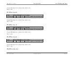
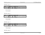
– Sets the hysteresis polarity:
–
0: Comparator trips when Vp
>
Vn + Vhys
–
1: Comparator trips when Vp
<
Vn – Vhys
•
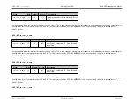
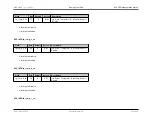
– Allows user to trade off comparator power for speed with four different bias current settings:
–
0: 0.52uA, 4.0us delay (default)
–
1: 1.4uA, 1.7us delay
–
2: 2.8uA, 1.1us delay
–
3: 5.1uA, 0.7us delay
•
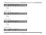
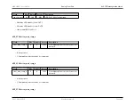
– Allows either or both n-channel and p-channel input stages to be selected for the low-power comparator:
–
0: Both n-channel and p-channel input stages selected (default)
–
1: Only n-channel stage input stage selected
–
2: Only p-channel stage input stage selected
–
3: Reserved
•
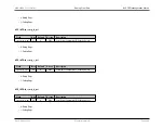
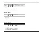
– Clears the corresponding wake-up detector for the specified comparator when set to 1
•
– Sets the comparator wakeup detector:
–
0: Wakeup detector is inactive (idle state)
–
1: Activates wakeup detector with falling edges
–
2: Activates wakeup detector with rising edges
–
3: Reserved
Each comparator has a direct output lpcmp[X] that drives into the
MAX32600
logic core. The primary purpose of the low-power comparators is to provide a low-power
means for detecting external events and wake the device from low-power sleep or stop modes. Each comparator has an associated wake-up detector, set by the
bits and cleared with the
bit.
has three states that control the mode of the wakeup detector:
Wakeup Detector Set Modes
in_mode_compX[1:0]
Mode
00
Idle
01
Activates on falling edge of lpcmp
10
Activates on rising edge of lpcmp
11
Reserved
Rev.1.3 April 2015
Maxim Integrated
Page 352
Содержание MAX32600
Страница 1: ...MAX32600 User s Guide April 2015...


