MAX32600 User’s Guide
Pin Configurations, Packages, and Special Function Multiplexing
5.5 Registers (GPIO)
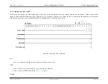
Returns current input value on this pin, as modified by the corresponding Input Monitoring Mode setting.
5.5.1.7
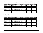
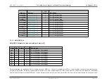
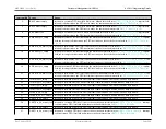
GPIO_INT_MODE_Pn
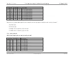
GPIO_INT_MODE_Pn.[pin0, pin1, pin2, pin3, pin4, pin5, pin6, pin7]
Field
Bits
Default
Access
Description
pin0
2:0
000b
R/W
Pn.0 GPIO Interrupt Detection Mode
pin1
6:4
000b
R/W
Pn.1 GPIO Interrupt Detection Mode
pin2
10:8
000b
R/W
Pn.2 GPIO Interrupt Detection Mode
pin3
14:12
000b
R/W
Pn.3 GPIO Interrupt Detection Mode
pin4
18:16
000b
R/W
Pn.4 GPIO Interrupt Detection Mode
pin5
22:20
000b
R/W
Pn.5 GPIO Interrupt Detection Mode
pin6
26:24
000b
R/W
Pn.6 GPIO Interrupt Detection Mode
pin7
30:28
000b
R/W
Pn.7 GPIO Interrupt Detection Mode
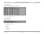
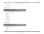
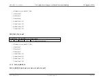
Sets interrupt detection condition for this pin.
• 000b: Disabled
• 001b: Detect interrupt on falling edge
• 010b: Detect interrupt on rising edge
• 011b: Detect interrupt on rising or falling edge
• 100b: Active low state interrupt detection
• 101b: Active high state interrupt detection
• 11xb: Disabled
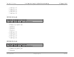
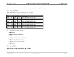
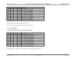
5.5.1.8
GPIO_INTFL_Pn
GPIO_INTFL_Pn.[pin0, pin1, pin2, pin3, pin4, pin5, pin6, pin7]
Rev.1.3 April 2015
Maxim Integrated
Page 191
Содержание MAX32600
Страница 1: ...MAX32600 User s Guide April 2015...

