


MAX32600 User’s Guide
System Clock, Timers/Counters, Watchdog Timers and Real Time Clock
10.3 Real Time Clock (RTC)
• Dedicated low-frequency, low-power 4kHz clock source (derived from 32kHz external crystal oscillator)
• Continued operation when main portion of system is powered off
–
Automatic switchover to operate from either main power supply or V
RTC
backup power supply
• 32-bit RTC timer
• Integrated prescaler determines interval between RTC timer ticks: from 244 microseconds (fastest RTC tick rate) to eight seconds (slowest RTC tick rate)
• Automatic synchronization of timers, configuration registers, and status/interrupt flags between high-frequency and 4kHz clock domains
• Two separate 32-bit timer compare registers allow a wakeup and/or interrupt event to occur when the RTC timer reaches a predetermined alarm value
• Integrated prescaler compare mask allows a wakeup and/or interrupt event to occur at a regular sub-RTC-tick interval (subsecond/interval alarm)
10.3.2
RTC Resets
The standard System Reset and Power-on Reset (POR) sources do not halt the operation of the RTC nor clear its register contents. Once the RTC has been
configured properly and the timer is running, the RTC will continue normal operation during System Reset and/or POR conditions.
Since the RTC has its own backup power supply (V
RTC
), it will only reset in the event that power fails on both the main supply (both V
DD
and V
BUS
) and the V
RTC
supply. In this case, the RTC will be reset and all associated RTC registers will be cleared to the default state. In the register description sections, this reset condition
is listed as "RTC POR".
The RSTN power sequencer reset pin does not affect the operation of the RTC and does not clear any
or
register contents.
Simply resetting the RTC oscillator (e.g., setting the
to 1) does not reset the RTC as a whole nor clear RTC register contents.
The RTC as a whole will be reset when it exits a shutdown state; the RTC may be shut down during certain power modes as controlled by the power sequencer. See
information in
for further details.
10.3.3
RTC Interrupts
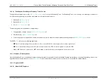
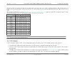
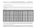
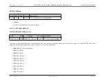
The RTC module reports interrupts to the CPU core using the following interrupt vector channels.
Interrupt Number
Vector
Interrupt Source
Description
26
0xa8
RTC Interrupt 0
RTC Time of Day Alarm 0 Interrupt (match between COMP0 and RTC timer)
27
0xac
RTC Interrupt 1
RTC Time of Day Alarm 1 Interrupt (match between COMP1 and RTC timer)
28
0xb0
RTC Interrupt 2
RTC Subsecond/Interval Alarm Interrupt (masked PRESCALE matches zero)
29
0xb4
RTC Interrupt 3
RTC Timer Overflow Interrupt, RTC Trim Adjust Interrupt
Rev.1.3 April 2015
Maxim Integrated
Page 564
Содержание MAX32600
Страница 1: ...MAX32600 User s Guide April 2015...


