MAX32600 User’s Guide
System Configuration and Management
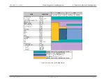
4.1 Power Ecosystem and Operating Modes
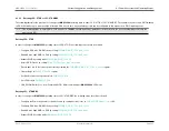
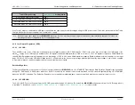
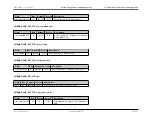
• Assert GPIO Freeze by setting
to 1
• Clear all flags in
register
• Set Run/Sleep mode of peripherals in
• Set LP1 mode in
• CM3_PWRMAN bit 2 to 1; Arm Command WFE – ARM command puts
MAX32600
in LP1 mode
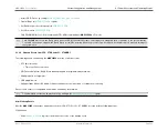
Note
CM3_PWRMAN bit 2 is is the ’Deep Sleep’ bit of the ARM Cortex-M3 System Control register. Setting this bit to 1 indicates to the system that the
Cortex-M3 clock can be stopped; the ’Deep Sleep’ port will be asserted when the processor can be stopped. Setting this bit to 0 prevents turning off
the system clock.
4.1.2.4
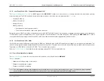
Wakeup Events from LP0: STOP and LP1: STANDBY
The following events can wake up the
MAX32600
from the Low Power states:
• RTC timer interrupt
–
Timer has 244us resolution
• GPIO sensed high/low (All GPIO are wakeup capable as programmed by firmware)
• Analog input to a comparator
• USB plugin/remove
• Supply Voltage Monitor (SVM) low voltage condition sensed via periodic or continuous monitoring
Each of these events is configurable and must be enabled by the firmware.
Note
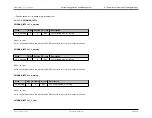
Certain wakeup events can be masked out by writing to the
register.
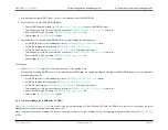
After Wakeup Events
After the
MAX32600
experiences a wakeup event from LP0: STOP or LP1: STANDBY, proceed with the following actions:
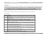
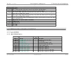
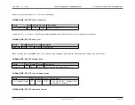
LP0 Wakeup
• Read
register to determine the source of the wakeup event
Rev.1.3 April 2015
Maxim Integrated
Page 33
Содержание MAX32600
Страница 1: ...MAX32600 User s Guide April 2015...


