MAX32600 User’s Guide
Analog Front End
8.5 LED
8.5.5
Fault Detection Setup
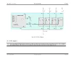
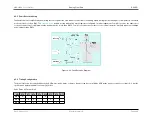
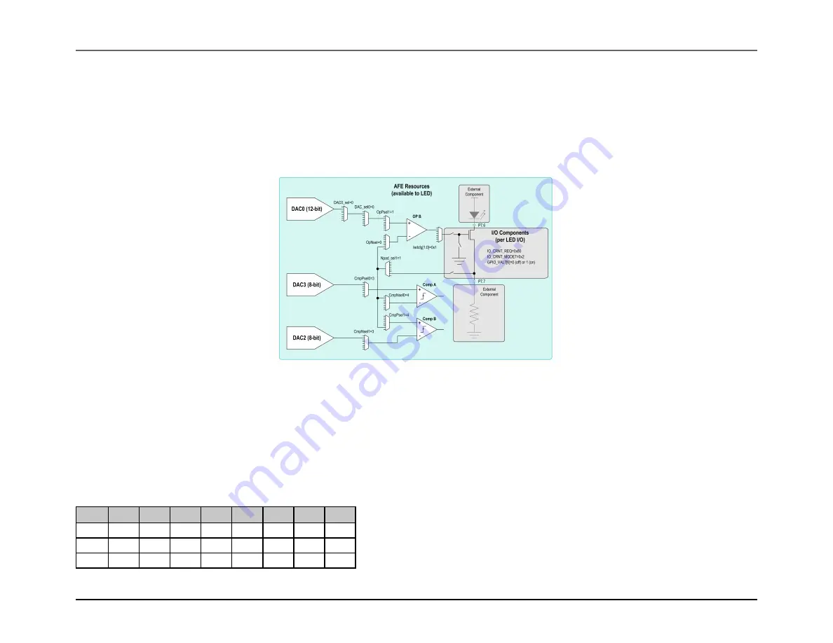
Fault detection is accomplished by monitoring the source pad of the sink, which is connected to the analog matrix, during operation by a pair of comparators, each with
a reference level set by a DAC. The
depicts a setup with switch matrix registers configured. In this arrangement, Comp0 is used as the undershoot
or open-circuit detector; it will trip when the feedback node is less than DAC2. Comp1 is used as the overshoot or short-circuit detector; it will trip when the feedback
node is greater than DAC3.
Figure 8.20: Fault Detection Diagram
8.5.6
Timing Configuration
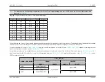
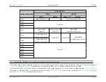
The driver state can be controlled directly by APB writes, pulse trains, or timers. Any port can be controlled by APB writes, any port can access timers 0-3, but the
specific pulse trains available for use vary by driver:
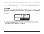
Pulse Trains by Current Sink
I/O
PT0
PT1
PT2
PT3
PT4
PT5
PT6
PT7
CS0
X
X
CS1
X
X
X
CS2
X
X
X
Rev.1.3 April 2015
Maxim Integrated
Page 486
Содержание MAX32600
Страница 1: ...MAX32600 User s Guide April 2015...

