MAX32600 User’s Guide
Analog Front End
8.2 AFE Reconfiguration Matrix
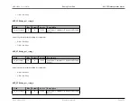
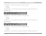
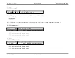
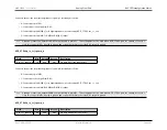
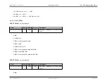
Connects the negative (inverting) input of op amp A internally as follows.
• 0: Connected to pin INA-
• 1: Connected to pin OUTA (voltage follower mode)
• 2: Connected to pin SCM[0-3] or to high impedance (as selected by AFE_CTRL2.scm_or_sel)
• 3: Connected to both pin SCM[0-3]/high impedance AND INA-
AFE_CTRL4.n_in_sel_opamp_b
Field
Bits
Default
Access
Description
n_in_sel_opamp_b
11:10
00b
R/W
Op Amp B Negative Input Select
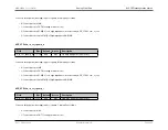
Connects the negative (inverting) input of op amp B internally as follows.
• 0: Connected to pin INB-
• 1: Connected to pin OUTB (voltage follower mode)
• 2: Connected to pin SCM[0-3] or to high impedance (as selected by AFE_CTRL2.scm_or_sel)
• 3: Connected to both pin SCM[0-3]/high impedance AND INB-
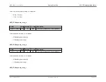
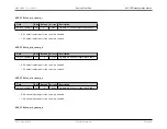
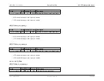
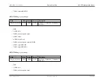
AFE_CTRL4.n_in_sel_opamp_c
Field
Bits
Default
Access
Description
n_in_sel_opamp_c
13:12
00b
R/W
Op Amp C Negative Input Select
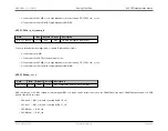
Connects the negative (inverting) input of op amp C internally as follows.
• 0: Connected to pin INC-
• 1: Connected to pin OUTC (voltage follower mode)
Rev.1.3 April 2015
Maxim Integrated
Page 392
Содержание MAX32600
Страница 1: ...MAX32600 User s Guide April 2015...

