MAX32600 User’s Guide
Analog Front End
8.5 LED
I/O
PT0
PT1
PT2
PT3
PT4
PT5
PT6
PT7
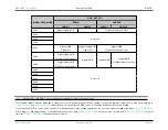
CS3
X
X
X
CS4
X
X
CS5
X
X
X
CS6
X
X
X
CS7
X
X
X
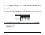
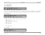
The advantages of timer or pulse train control are synchronous control with minimum jitter and simultaneous switch of multiple I/O. Though, pulse trains have limited
duty cycle with a maximum length of 32-bits and a minimum of at least 3.125% duty cycle, and timers only operate in a clock-like fashion.
8.5.7
Considerations
8.5.7.1
Design Current
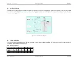
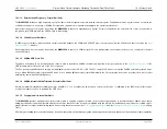
The design process for a precision current LED system involves balancing current resolution, supply voltage, and the operating forward voltage of the LED involved
to take advantage of the headroom available.
LED selection is usually determined by the desired wavelength (i.e., color output) and brightness; other components are adapted to fit the necessary requirements.
In many applications, the LED uses the majority of the supply voltage, and the requirement will be to minimize the headroom of the NMOS switch and sense resistor.
In the case of an H-bridge configuration, the headroom of the PMOS switch will need to be factored in as well.
Reducing the sense resistor directly results in loss of current resolution and introduces limitations in setting the current. This must be considered as precision is
important in certain applications. Also, loss of resolution makes the current loop more susceptible to ground drop. For a 50mA output, 9-bits of resolution yields step
sizes of 100uA. With the 12-bit DAC as the driver, this means that the sense voltage needs to be at least 12.5% of V
REFDAC
; for a 2.5V reference voltage, the sense
voltage must be at least 312.5mV.
Ground drop remains a concern and is a key factor of accuracy. To maintain accuracy at the 0.1% level of a precision resistor and 9-bits on the DAC, the ground drop
should be less than 0.1% of sense voltage. Also, with currents at 100mA, parasitic resistance can be significant. Typical sense resistors that translate to 0.3-0.6mV
or parasitic resistances on the order of 3-6mOhms keep the effects of parasitic resistance minimized.
8.5.7.2
Average and Peak Current
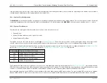
The absolute maximum steady state current allowed through a single switch is 135mA at 85°C. When multiple switches are arranged in parallel, however, the split
of the current between the parallel devices is dependent on threshold and metal resistance differences. Although the division of current between multiple I/Os is
constant for a particular part, it is not a controlled or specified parameter.
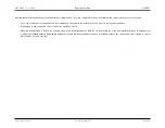
It is recommended that parts with a high duty cycle and multiple I/O connected in parallel do not exceed an average current of 200mA. Transient currents will be
limited by the switch Ids to a point that is safe for the
MAX32600
. Transient currents may damage external components or possibly have safety implications—it is
Rev.1.3 April 2015
Maxim Integrated
Page 487
Содержание MAX32600
Страница 1: ...MAX32600 User s Guide April 2015...


