MAX32600 User’s Guide
LCD Controller
13.3 LCD Configuration
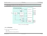
• 1/3 duty multiplexed with 1/3 bias voltages (COM [0:2])
• 1/4 duty multiplexed with 1/3 bias voltages (COM [0:3])
Note
Since the voltages available for LCD drive are
V
LCD
,
V
LCD
×
2
3
,
V
LCD
×
1
3
, and
V
ADJ
, the
1
2
-bias mode (which requires an output level of
V
LCD
×
1
2
) will
require two of the LCD voltage output pins (V
LCD2
and V
LCD1
) to be shunted together externally.
Due to the area under the curve, this duty multiplexing produces a lower contrast display in non-static operation. If the hardware has the same amount of time to
multiplex two common drivers (COMx) as it does for dedication to one common driver (static operation), the display for the two COMx will be effectively dimmer. Here,
the multiplex spends half of its time working on COM0, for instance, and the other half on COM1.
13.3
LCD Configuration
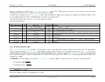
LCD power and clock registers must be configured first to ensure proper device configuration. If a clock is off to the block, writes to the APB registers may not be
recognized.
13.3.1
LCD Clock
The
MAX32600
LCD controller uses the device’s on-board 32kHz RTC as a source clock. Comprehensive configuration details for the RTC can be found in the
section. To enable the RTC for the LCD controller,
must be in its default state of 0 and
needs to be set to 1 to enable operation in run mode.
Additionally, the clock manager charge pump,
CLKMAN_CLK_CTRL_8_LCD_CHPUMP.lcd_clk_scale
, must be configured. Writing 0001b to this field enables CLK
= (System Clock Source / 1). Writing 0000b to this field disables the CLK and is the default following a reset.
13.3.2
LCD Power Control
The power control register of the LCD controller must be enabled in conjunction with the clock charge pump outlined above. Writing 1 to the
field enables power to the controller. Writing 0 to this field powers down the controller.
13.3.3
LCD Configuration Registers
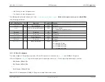
The initial startup of the LCD controller requires two writes to
. First, write 1 to
to enable the LCD display. Second, write 1 to both
and
. The LCD display enable bit must be written twice because the resistor divider can only be configured in
“suspend” mode (i.e., OPM=0) but with the display already enabled (i.e., DPE=1).
Rev.1.3 April 2015
Maxim Integrated
Page 637
Содержание MAX32600
Страница 1: ...MAX32600 User s Guide April 2015...


