MAX32600 User’s Guide
Analog Front End
8.5 LED
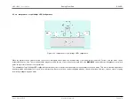
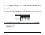
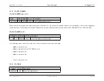
For the compact packages (7mm x 7mm and WLP packages) switching between sink and source is more simple. Set the
to 0x7 and use
to switch between sink and source. Since
can be controlled by a pulse train, this off loads the PMU and ARM processors
and provides deterministic timing.
NOTE
: As is is available only in mode 0x7, op amps B or D must be used. In the WLP package, op amp D is not available
externally, so it is the ideal candidate to manage the LED control loops.
8.5.4
Control Loop Setup
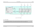
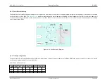
An op amp from the AFE must be used to achieve a regulated current in Current Mode. As depicted in the
, the source pad is fed back to the
op amp’s negative input, and the positive input is the command voltage (coming from a DAC in this case). An alternative option is to use the uncommitted switches
and ground switches to dynamically switch the command voltage. Additionally, the command voltage can originate from an external source using the positive input
pad of the op amp.
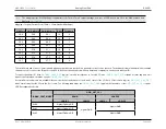
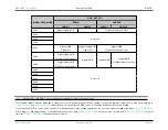
First, the connection from the op amp to the appropriate current sink must be established. Modify the
and
fields, as shown below:
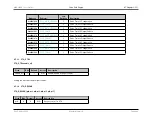
AFE_CTRL0.led_cfg
State
Channel 0
Channel 1
1:0
0x00
OpAmp A
N/A
0x01
OpAmp B
N/A
0x02, 0x03
Disabled
N/A
3:2
0x00
N/A
OpAmp C
0x01
N/A
OpAmp C
0x02, 0x03
N/A
Disabled
Note
If a control voltage needs to be driven from outside the part, the
and
fields still need to select
an op amp, but that op amp must be powered down.
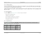
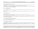
In addition to the LED configuration settings, the following components must typically be set up:
• Op amp power mode and source selection
• DAC power and data value selection
• Reference voltage selection
Rev.1.3 April 2015
Maxim Integrated
Page 485
Содержание MAX32600
Страница 1: ...MAX32600 User s Guide April 2015...


