MAX32600 User’s Guide
System Clock, Timers/Counters, Watchdog Timers and Real Time Clock
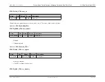
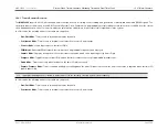
10.4 Timers/Counters
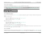
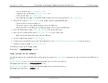
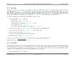
2. Write to the Timer register to set the starting count value,
or
, depending on which one of the 16-bit timers
is being used
• This only affects the first, starting, operation
• After the first Timer Compare in Continuous Mode, counting always begins at the reset value of 0x0001
3. Write the Compare Count value,
or
4. If desired, enable the timer interrupt,
or
5. Enable timer and start counting,
or
= "1"
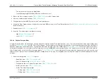
In Continuous Mode, the currently selected System Clock always provides the timer input. The timer period is given by the following equation:
Continuous Timeout Period
(
s
) =
ReloadValue
SystemClockFrequency
(
Hz
)
×
Prescale
If an initial starting value other than 0x0001 is loaded into the Timer register, the
equation must be used to determine the first time-out period.
10.4.4
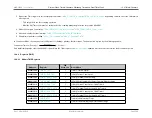
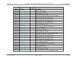
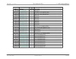
Registers (TMR)
10.4.4.1
Module TMR Registers
Address
Register
32b
Word Len
Description
0x40012000
1
Timer Control Register
0x40012004
1
[32 bit] Current Count Value
0x40012008
1
[32 bit] Terminal Count Setting
0x4001200C
1
[32 bit] PWM Compare Setting or Capture/Measure Value
0x40012010
1
[16 bit] Current Count Value, 16-bit Timer 0
0x40012014
1
[16 bit] Terminal Count Setting, 16-bit Timer 0
0x40012018
1
[16 bit] Current Count Value, 16-bit Timer 1
0x4001201C
1
[16 bit] Terminal Count Setting, 16-bit Timer 1
0x40012020
1
Timer Module Interrupt Flags
0x40012024
1
Timer Module Interrupt Enable/Disable Settings
Rev.1.3 April 2015
Maxim Integrated
Page 598
Содержание MAX32600
Страница 1: ...MAX32600 User s Guide April 2015...

