MAX32600 User’s Guide
System Clock, Timers/Counters, Watchdog Timers and Real Time Clock
10.4 Timers/Counters
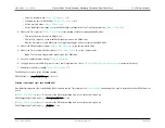
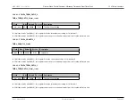
2. Write to the Timer register to set the starting count value, typically 0x0000_0001
3. Write to the Timer Compare register,
, to set the Compare value
4. If desired, enable the timer interrupt,
5. Configure the associated GPIO port pin for the Timer Input function
6. Enable the timer,
= "1"
7. Counting begins after the first desired transition of the Timer Input signal
• No interrupt is generated by this first edge.
In Capture/Compare mode, the elapsed time from timer start to the Capture event can be calculated using the following equation:
Capture Elapsed Time
(
s
) =
(
CaptureValue
−
StartValue
)
×
Prescale
SystemClockFrequency
(
Hz
)
10.4.3
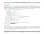
16 bit Mode Timer Operation
Each of the four 32-bit timers on the
MAX32600
can be split into 2 x 16-bit timers, for a total of up to eight 16-bit timers. Configuration and operation of 16-bit mode
is very similar to the 32-bit modes of operation, but when configured as two 16-bit timers, only One-Shot and Continuous Modes of operation are supported.
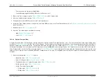
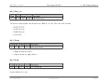
Minimum time-out delay for each 16-bit timer is set by:
• Loading the value 0x0001 into the Timer Compare register, either the
or
• Setting the prescale value to 1 in the
field
Maximum time-out delay is set by:
• Loading the value 0x0000 into the Timer Compare register,
or
• Setting the prescale value to 4096 in the
• If the Timer reaches 0xFFFF, the timer rolls over to 0x0000 and continues counting
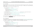
The current count value,
or
, in the timers can be read while the timer is counting and enabled. This action does
not affect the timer’s operation.
As a general rule, the timer output is toggled every time the counter is reloaded.
Rev.1.3 April 2015
Maxim Integrated
Page 596
Содержание MAX32600
Страница 1: ...MAX32600 User s Guide April 2015...

