


MAX32600 User’s Guide
Pulse Train Engine
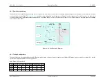
9.6 Synchronization
9.5.2
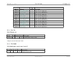
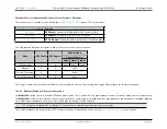
Square Wave Mode
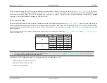
In Square Wave mode, the PTE simply toggles the output state when the rate counter, as defined in the
field, expires. In Square
Wave mode, if the rate is set to a value of 1, the Pulse Train Peripheral clock rate is output directly.
Square Wave Mode Rate Control Table
rate_control (27-bit value)
Frequency Out
1
(PTE
PCLK
)
2
(PTE
PCLK
/2)
3
(PTE
PCLK
/4)
4
(PTE
PCLK
/6)
5
(PTE
PCLK
/8)
In general, for Rates
>
1 the output frequency is determined by the equation:
f
out
=
(
PT E
PCLK
)
(
2
×
(
rate
_
control
−
1
))
Where PTE
PCLK
is the Pulse Train Peripheral Clock and rate_control is a 27-bit value for the divisor set using the
register field.
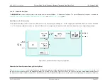
9.6
Synchronization
The Pulse Train Engine supports the synchronization of multiple Pulse Train outputs. To synchronize the outputs of one or more Pulse Trains, set the corresponding
bit(s) in the
register. Writing to this register resets the output sequence of all affected pulse trains to the beginning of the pattern defined in the
register (with the LSB being sent out first), and also resets the output state for any affected pulse trains which are in square wave mode.
Note
The Pulse Train Engine configuration registers may be modified at any time by the user. If the PTE is active when these registers are modified, the
output state is immediately affected and might result in undesired or unintended effects on the output.
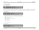
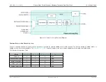
9.7
Registers (PT)
9.7.1
Module PT Registers
Rev.1.3 April 2015
Maxim Integrated
Page 492
Содержание MAX32600
Страница 1: ...MAX32600 User s Guide April 2015...


