


MAX32600 User’s Guide
Introduction
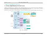
2.7 Digital Peripherals
2.7.7
USB 2.0 Device Slave with Integrated Transceiver
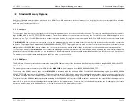
The integrated USB controller is compliant with the USB 2.0 specification, providing full-speed operation as a USB peripheral device. Integrating the USB physical
interface (PHY) allows direct connection to the USB cable, reducing board space and overall system cost. An integrated voltage regulator enables smart switching
between the main supply and V
BUS
when connected to a USB host controller.
The USB Controller contains an integrated AHB bus master which it uses to write to and read from the buffers for each supported/active endpoint. These buffers are
located in the standard system SRAM (in user-configurable locations), so they can also be accessed by firmware directly as well as by the USB DMA engine. A total
of seven endpoint buffers are supported with configurable selection of IN or OUT in addition to endpoint 0, which is read-only.
2.7.8
LCD Controller
The
MAX32600
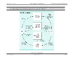
incorporates an LCD controller with a boost regulator that interfaces to common low-voltage displays in the standard 12mm x 12mm package. By
incorporating the LCD controller into the microcontroller, the design requires only an LCD glass rather than a considerably more expensive LCD module. Every
character in an LCD glass is composed of one or more segments, each of which is activated by selecting the appropriate segment and common signal.
The microcontroller can multiplex combinations of up to 40 segment outputs (SEG0 to SEG39) and four common signal outputs (COM0 to COM3). Unused segment
outputs can be used as general-purpose port pins. The segments are easily addressed by writing to dedicated display memory. Once the LCD controller settings
and display memory have been initialized, the 21-byte display memory is periodically scanned, and the segment and common signals are generated automatically
at the selected display frequency. No additional processor overhead is required while the LCD controller is running. Unused display memory can be used for
general-purpose storage.
The design is further simplified and cost reduced by the inclusion of software-adjustable internal voltage-dividers to control display contrast, using either V
DDIO
or an
external voltage. If desired, contrast can also be controlled with an external resistor network.
The features of the LCD controller include the following:
• Automatic LCD segment and common-drive signal generation
• Integrated boost regulator ensures LCD operation down to 2V
• Flexible LCD clock source selection
• Adjustable frame frequency
• Internal voltage-divider resistors eliminate requirement for external components
• Internal adjustable resistor allows contrast adjustment without external components
Four display modes are supported by the LCD controller:
• Static (COM0)
Rev.1.3 April 2015
Maxim Integrated
Page 20
Содержание MAX32600
Страница 1: ...MAX32600 User s Guide April 2015...


