MAX32600 User’s Guide
Analog Front End
8.2 AFE Reconfiguration Matrix
Single-Pole, Single-Throw (SPST)
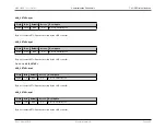
Similarly the four SPST pins SNO0/1/2/3 are selected by a 4:1 mux using register field
creating the signal sno_or.
selects between the four
SPST pins SCM0/1/2/3 creating the signal scm_or. SPST switches 2 and 3 are only available in the 12mm x 12mm package and cannot be selected in the 7mm x
7mm or WLP packages.
The sno_or signal is common to all four Analog Reconfiguration Matrices. The SPST switches must be disabled if these pins are to be used as matrix inputs and not
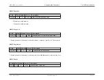
as SPST switch pins as signals may be shorted to one another in undesirable ways. Writing 0 to the following registers opens (disables) the corresponding SPST
switches:
, and
. It is possible, however, to use one side of an SPST switch as an op amp input in which case the
switch could be closed and still be used in the matrices. The user must understand the nature of each of the signals connected to the matrix to avoid situations where
the impedance of the closed switch might create undesired currents or loads.
LED Observe Ports
The LED observe ports 0 and 1 are available as Analog Reconfiguration matrix inputs. Two LED drive control multiplexers allow op amp outputs OUTA or OUTB to
drive LED Sink Port 0 and OUTC or OUTD to drive LED Sink Port 1. A third mux state drives V
SS
onto LED Sink Port 0 or LED Sink Port 1 disabling the LED sink
devices. This is the power-up default condition for the part.
Channel Select Register
The
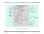
can select various signals to drive into the ADC input as noted in the
Analog Reconfiguration Sub-Matrix Diagram
. Specifically, each of the four op
amp outputs OUTA/B/C/D, INA+, and the mux switch pins scm_or or sno_or. The
can also select a number of other signals for the ADC as described
in the
ADC Input Multiplexer Configuration Section
External Pins
The above mentioned dac0, dac1, sno_or, scm_or, and LED Observe Port 0 and 1 signals along with the two 8-bit DAC outputs DAC2p and DAC3p comprise the
eight signals that drive into all four of the analog reconfiguration matrices. The 16 external pins, however, are specific to each of the four analog reconfiguration
matrices as follows:
Analog Reconfiguration Matrix External Pin Table
Analog
Reconfiguration
Matrix
DACOUT
Op Amp Positive
Input
Op Amp Negative
Input
Op Amp Output
LED Observe Port
Input
SCM Pin
SNO Pin
0
SCM0
INA+
INA-
OUTA
0
SCM0
SNO0
1
SNO0
INB+
INB-
OUTB
0
SCM1
SNO1
2
SCM1
INC+
INC-
OUTC
1
SCM2
SNO2
Rev.1.3 April 2015
Maxim Integrated
Page 349
Содержание MAX32600
Страница 1: ...MAX32600 User s Guide April 2015...

