MAX32600 User’s Guide
Communication Peripherals
7.2 SPI
7.2.5
SPI Fast Mode
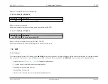
Setting up SPI “Fast Mode” is done by setting the
and
fields to 0000b. This sets the SPI SCK clock to a
gated version of the system clock, based on the SPI Clock Configuration.
Additional configuration options are supported and are detailed in the
register.
7.2.6
Communication and Data Transfer
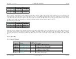
Once the SPI has been configured to communicate with a specific slave, SPI transactions are initiated by writing to the SPI Transaction FIFO mapped into the AHB
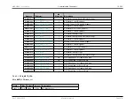
system address map. See
for transmit FIFO details for each SPI port. Prior to initiating a transaction, both the TX and RX SPI FIFOs need to be enabled.
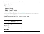
To enable the Transmit FIFO, set register field
for the specific SPI peripheral being used. The Receive FIFO is enabled by setting
to 1.
The FIFO is 16-bits wide and expects a 16-bit header followed by an optional payload padded out to a 16- bit boundary.
If the transaction generates results data, this data is pushed onto the SPI Results FIFO mapped into the AHB system address map. See (
) for receive
FIFO details for each SPI port. This FIFO is 8- bits wide and will zero-pad to a byte boundary at the completion of a SPI transaction.
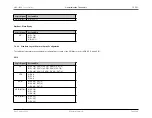
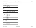
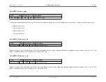
The format of the header is as follows:
SPI Transaction Header
Bit
Mnemonic
Description
[1:0]
Direction
Direction of information transfer with respect to the Master.
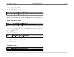
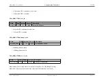
• 0 = None
• 1 = TX
• 2 = RX
• 3 = Both
For headers which do not define a transmission (i.e., Direction = None or Rx), no payload is required. Conversely, headers which do not
define a reception (i.e., Direction = None or Tx), result in no data being pushed onto the results FIFO.
Rev.1.3 April 2015
Maxim Integrated
Page 267
Содержание MAX32600
Страница 1: ...MAX32600 User s Guide April 2015...


