MAX32600 User’s Guide
System Clock, Timers/Counters, Watchdog Timers and Real Time Clock
10.4 Timers/Counters
10.4.2.5
Capture Mode
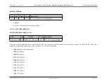
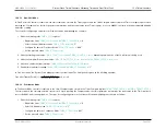
In Capture Mode, the current timer count value is recorded when the desired external Timer Input transition occurs. The Capture Mode count value is stored in the
Timer PWM register. The
bit in the Timer Control register determines if the Capture occurs on a rising edge (TMRn_CTRL.polarity = “0”) or a
falling edge (TMRn_CTRL.polarity = “1”) of the Timer Input signal. When the Capture event occurs, an interrupt is generated, and the timer continues counting. The
timer continues counting up to the 32-bit compare value stored in the Timer Compare/Match register,
. Upon reaching the Compare value, the
timer generates an interrupt, the count value in the Timer count register
is reset to 0x0000_0001, and counting resumes.
The steps for configuring a timer for Capture Mode and initiating the count are as follows:
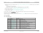
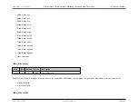
1. Write the following in the
register:
• Disable the timer,
= “0”
• Select 32-bit timer mode,
= "0"
• Configure the timer for Capture Mode,
= “100”
• Set the prescale value,
• Set the Capture edge (rising or falling) for the Timer Input,
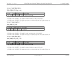
2. Write to the Timer Count register,
, to set the starting count value, typically 0x0000_0001
3. Write to the Timer Compare register,
, to set the Compare value
4. If desired, enable the timer interrupt,
5. Configure the associated GPIO port pin for the Timer Input function
6. Enable timer and start counting,
= "1"
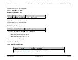
In Capture mode, the elapsed time from timer start to Capture event can be calculated using the following equation:
Capture Elapsed Time
(
s
) =
(
CaptureValue
−
StartValue
)
SystemClockFrequency
(
Hz
)
×
Prescale
10.4.2.6
Compare Mode
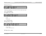
In Compare Mode, the timer counts up to the compare value stored in the Timer Compare register. Upon reaching the compare value, the timer generates an interrupt
and counting continues (the timer value is not reset to 0x0000_0001). Also, if the Timer Output function is enabled (in the GPIO), the Timer Output pin changes
state (from Low to High or from High to Low) upon a Compare Match. When the Timer reaches 0xFFFF_FFFF, the timer rolls over to 0x0000_0000 and continues
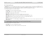
counting. The steps for configuring a timer for Compare mode and initiating the count are as follows:
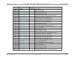
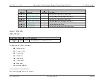
1. Write the following to the
register:
Rev.1.3 April 2015
Maxim Integrated
Page 593
Содержание MAX32600
Страница 1: ...MAX32600 User s Guide April 2015...

