MAX32600 User’s Guide
Analog Front End
8.5 LED
Note
The mapping of the WLP Package is equivalent to the 7mm x 7mm Compact package; however, all LED drivers are 2X on the WLP (replace drive
figures in
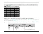
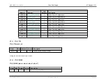
Mapping of Logical Current Ports (12mm x 12mm Standard Package)
Sink Port
Switch Drain
Switch Source
Drive
Feedback
CS0
P6.0
P6.1
1X
0
CS1
P6.2
P6.3
1X
0
CS2
P6.4
P6.5
1X
1
CS3
P6.6
P6.7
1X
1
CS4
P7.0
P7.1
1X
0
CS5
P7.2
P7.3
1X
0
CS6
P7.4
P7.5
1X
0
CS7
P7.6
P7.7
1X
0
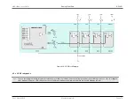
The switch drain and source columns indicate which physical balls are involved in a particular current source function. The feedback column indicates which feedback
channel is used to connect the I/O back to the AFE, which subsequently affects which op amps and comparators can be used with that I/O.
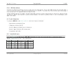
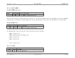
To request particular I/O, write to
register; each bit corresponds to one sink I/O pair.
contains a status flag, and if all
requests were granted, should be equal to
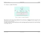
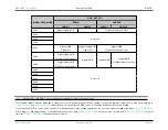
Several different sub-modes are available; these modes define the behavior of the 0 and 1 states of the I/O. Each I/O port has a register,
which controls whether the I/O is in the 0 or 1 state. The following table maps the
against the two values of the
register.
LED Reconfiguration Modes
GPIO_OUT_VAL
DRAIN
SOURCE
IOMAN_CRNT_MODE
LOGIC 1
LOGIC 0
LOGIC 1
LOGIC 0
0x00
N-gate=OpAmp A/B
N-gate=GND
N-gate=GND
0x01
N-gate=OpAmp C/D
0x02
N-gate=OpAmp A/B
N-gate=GND
Rev.1.3 April 2015
Maxim Integrated
Page 483
Содержание MAX32600
Страница 1: ...MAX32600 User s Guide April 2015...


