MAX32600 User’s Guide
System Clock, Timers/Counters, Watchdog Timers and Real Time Clock
10.4 Timers/Counters
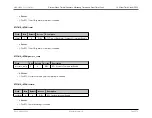
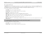
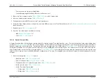
• Select 32-bit timer mode,
= "0"
• Configure the timer for PWM Mode,
= “011”
• Set the prescale value,
• Set the initial logic level (High or Low) and PWM High/Low transition for the Timer Output function,
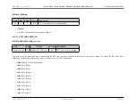
2. Write to the Timer register,
, to set the starting count value (typically 0x0000_0001)
• This only affects the first pass in PWM mode
• This value is only used on the initial PWM signal pass when the PWM starts
• After the first timer reset in PWM mode, counting always begins at the reset value of 0x0000_0001
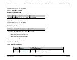
3. Write to the PWM Compare register,
, to set the desired match value
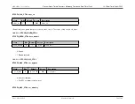
4. Write to the Timer Compare/Match register,
, to set the Compare value
•
Note
: The Compare value must be greater than the PWM value
5. If desired, enable the timer interrupt
6. Configure the associated GPIO port pin for the Timer Output function. (See
GPIO Pins and Peripheral Mode Functions
for further information.)
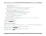
7. Enable timer and start counting,
= "1"
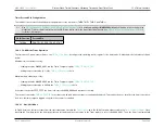
The PWM period is given by the following equation:
PWM Period
(
s
) =
ReloadValue
SystemClockFrequency
(
Hz
)
×
Prescale
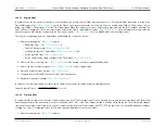
Starting count values other than 0x0000_0001
If an initial starting value other than 0x0000_0001 is loaded into the Timer register, the
equation must be used to determine the first PWM time-out
period.
If
is set to “0”, the ratio of the PWM output High time to the total period is given by:
PWM Output High Time Ratio
(
%
) =
(
ReloadValue
−
PW MValue
)
ReloadValue
×
100
If
is set to “1”, the ratio of the PWM output High time to the total period is given by:
PWM Output High Time Ratio
(
%
) =
PW MValue
ReloadValue
×
100
Rev.1.3 April 2015
Maxim Integrated
Page 592
Содержание MAX32600
Страница 1: ...MAX32600 User s Guide April 2015...

