


Internal control/status words
Function diagrams
2-411
Siemens AG 2004 All Rights Reserved
SINAMICS G List Manual, Edition 12.2004
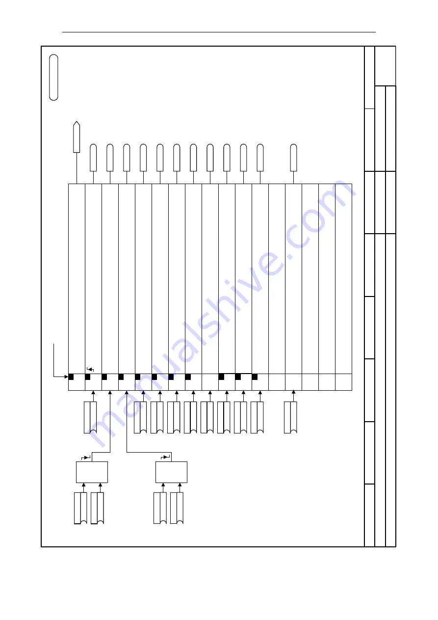
Picture 2-33 2501 – Control word sequence control
- 2501 -
8
7
6
5
4
3
2
1
fp_S01_2501_en.vsd
DO: VECTOR
SINAMICS G
17.12.04
V02.02.00
Internal control/status words, control word sequence control
p0844[C]
(1)
1 OFF2 (electrical)
p0845[C]
(1)
2 OFF2 (electrical)
p0848[C]
(1)
1 OFF3 (fast stop)
p0849[C]
(1)
2 OFF3 (fast stop)
11
12
13
14
15
p0840[C]
(0)
OFF1
p0852[C]
(1)
p1140[C]
(1)
p1141[C]
(1)
p1142[C]
(1)
PROFIdrive b
it
<1>
Bit 10 must be set in the first PZD word of the telegram received
from the serial interface in order that the drive accepts the
process data.
10
7
6
5
4
3
2
1
0
Bit No.
&
<2>
<2>
<4>
<2>
PROFIBUS interconnection:
For PROFIBUS standard telegrams, the upper inputs are
connected to PROFIBUS-STW1 [2420].
This only involves CDS0.
2000.00 µs
p0854[C]
(1)
r0898.0
r0898.1
r0898.2
r0898.3
r0898.4
r0898.5
r0898.6
r0898.10
r0898
STW sequence ctrl
p0855[C]
(0)
r0898.7
9
8
p1055 [C]
(0)
p1056 [C]
(0)
r0898.8
r0898.9
<3>
<3>
<3>
<3>
<3>
<3>
<3>
<3>
<3>
<3>
When the master control is retrieved, entered from STARTER
o
r
AOP30.
<3>
<3>
To jogging [3030.6]
To jogging [3030.6]
To the brake control [2701.4]
To the expanded brake control
[2707.1]
To the setpoint channel
[3060.1] [3070.1] [3080.4]
To the setpoint channel [3060.1]
[3070.1]
To the setpoint channel
[3060.6] [3070.7] [3080.5]
To the control unit
[2610]
To the control unit
[2610]
To the control unit
[2610]
To the control unit
[2610]
r0898.12
To the expanded brake control
[2707.1]
p0856[C]
(1)
Control word sequence control
1 = Operating condition, no coast-down active
(OFF2 inactive)
0 = Coast-down active (OFF2 active), pulse inhibit, motor coasts do
w
n
1 = Operating condition, no fast stop active
(OFF3 inactive)
0 = Fast stop active (OFF3 activ
e
)
1 = Unconditionally open the holding brake
1 = Control via PLC
Reserved
Reserved
Reserved
<1>
Reserved
1 = Jog, bit 0
1 = Jog, bit 1
1 = Enable speed controller
0 = Set speed controller to zero (I component and controller output)
= ON (pulses can be enabled)
0 = OFF1
(braking with ramp-function generator, then pulse cancellation and ready-to-
power-up)
1 = Start the ramp-function generator
0 = Stop the ramp-function generator (freeze the ramp-function generator outpu
t)
1 = Enable ramp-function generator
0 = Inhibit ramp-function generator (set the ramp-function generator output to zero)
1 = Enable setpoint
0 = Inhibit setpoint (set the ramp-function generator input to zer
o
)
1 = Enable operation
(pulses can be enabled)
0 = Inhibit operation (cancel pulses)
<4>
The path from [2711.6] is only valid for the expanded function module "expanded brake control (r0108.14 = 1)".
<4>
&
Function diagram


