background image

4-260


Chapter 4  OPERATION

4

1

2

3

5

6

7

8

9

10

Chapter 4  OPERATION


4-261

12. "SYSTEM" mode

5.  Condition for area check output

Selects the condition that allows the area check output to turn on, from either when the robot is 
within a specified area or when outside it.

n

NOTE 

•  Any point on the boundary of the specified area is determined to be within the  

   area. 

•  If the area check cannot be performed correctly due to return-to-origin  


   incomplete, operation other than "MANUAL" or "AUTO" mode, or a memory error,  
   then the area check output will turn off regardless of the criterion setting.If the  
   specified port is the same as the port used by the program, then the area check  
   output has priority. 

•  The default setting is "IN" (output is on within specified area).

1

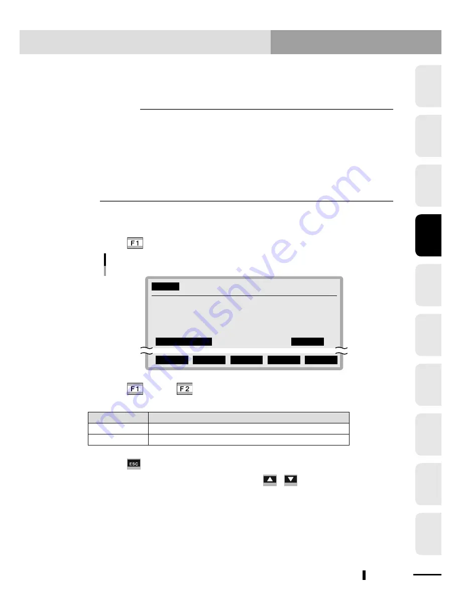
Select "5. Condition" in "SYSTEM>OPTION>POS.OUT>SELECT" mode.

2

Press 

 (EDIT).

SYSTEM

>OPTION>POS.OUT>SELECT    V10.01

  1.Output of area1           MAIN

  2.Output port1(DO & SO)     20

  3.Compare Point number11    P1

  4.Compare Point number12    P2

  5.Condition                 IN

 IN      OUT

Criterion selection for area check output

3

Press 

 (IN) or 

 (OUT) to select the criterion for area check 

output.

Setting

Meaning

IN

Turns on when the robot enters a specified area.

OUT

Turns on when the robot goes out of a specified area.

4

Press 

 to quit the editing.

To continue setting other items, use the cursor ( 

 / 

 ) keys to select them.

Summary of Contents for RCX240

Page 1: ...RCX240 EUR6127206 E107 Ver 2 06 Userʼs Manual YAMAHA 4 AXIS ROBOT CONTROLLER ...

Page 2: ......

Page 3: ... to install and operate the YAMAHA robot controller Be sure to read this manual carefully as well as related manuals and comply with their instructions for using the YAMAHA robot controller safely and correctly Refer to the Programming Manual that comes with the robot controller for detailed information on robot programs ...

Page 4: ... without connecting the absolute batteries so the origin position cannot be detected This means the robot connected to this controller cannot be used with absolute specifications 3 When connecting robot cables to the robot controller Be sure to keep robot cables separate from the robot controller power connection lines and other equipment power lines Using in close contact with lines carrying powe...

Page 5: ... wear out prematurely 5 Duty To achieve maximum service life for the single axis robots the robot must be operated within the allowable duty 50 The duty is calculated as follows Duty Operation time Operation time Non operation time 100 If the robot duty is too high an error such as overload or overheat occurs In this case increase the stop time to reduce the duty ...

Page 6: ...mpiling method 2 for rapid execution of programs 1 Standard Language for Industrial Manipulators 2 This compiling method checks the syntax in a robot language program converts it into intermediate codes and creates an execution file object file before actually performing the program 3 Movement command Arch motion Spatial movement during pick and place work can be freely set according to the work e...

Page 7: ... safety points 1 5 2 5 Safety precautions during robot operation 1 7 2 6 Precautions for disposal 1 7 3 Safety measures for robots 1 8 3 1 Safety measures for SCARA type robots 1 8 3 2 Safety measures for single axis robots Cartesian robots and pick place robots 1 8 4 Motor overload precautions 1 8 5 Warning labels and marks 1 8 5 1 Warning labels 1 8 5 2 Warning marks 1 9 6 Industrial robot opera...

Page 8: ...packing 3 1 1 1 Packing box 3 1 1 2 Unpacking 3 1 2 Installing the robot controller 3 2 2 1 Installation conditions 3 2 2 2 Installation methods 3 3 3 Connector names 3 6 4 Connecting to the power 3 7 4 1 Power supply connection example 3 7 4 2 Power supply and ground terminals 3 8 4 3 AC power connector wiring 3 9 4 4 Considering power capacity and generated heat amount 3 10 4 5 Installing an ext...

Page 9: ...3 27 13 3 Operation check 3 28 Chapter 4 OPERATION 1 Operation overview 4 1 2 The RCX robot controller 4 2 2 1 Part names 4 2 2 2 Main functions 4 2 3 RPB programming box 4 3 3 1 Part names 4 3 3 2 Main functions 4 3 3 3 Connection to the robot controller 4 5 3 4 Changing the RPB screen settings 4 6 4 Turning power on and off 4 7 5 Operation keys 4 9 5 1 RPB screen 4 9 5 2 Operation key layout 4 1...

Page 10: ...command execution 4 52 9 9 Break point 4 53 9 9 1 Setting break points 4 53 9 9 2 Deleting break points 4 54 9 10 Executing a step 4 55 9 11 Skipping a step 4 56 9 12 Executing the next step 4 56 10 PROGRAM mode 4 57 10 1 Scrolling a program listing 4 58 10 2 Program editing 4 59 10 2 1 Cursor movement 4 61 10 2 2 Insert Overwrite mode switching 4 62 10 2 3 Inserting a line 4 63 10 2 4 Deleting a ...

Page 11: ...t comment 4 108 11 2 8 4 Copying a point comment 4 109 11 2 8 5 Erasing point comments 4 110 11 2 8 6 Point comment search 4 111 11 2 9 Point data error reset 4 112 11 3 Displaying editing and setting pallet definitions 4 113 11 3 1 Editing pallet definitions 4 115 11 3 1 1 Point setting in pallet definition 4 116 11 3 1 1 1 Editing the point in pallet definition 4 117 11 3 1 1 2 Setting the point...

Page 12: ...ial I O setting 4 237 12 1 6 3 Setting the network parameters 4 240 12 2 Communication parameters 4 242 12 3 OPTION parameters 4 252 12 3 1 Setting the area check output 4 253 12 3 2 Setting the SERVICE mode 4 262 12 3 2 1 Saving the SERVICE mode parameters 4 267 12 3 2 2 Help display in SERVICE mode 4 268 12 3 3 SIO settings 4 269 12 3 4 Double carrier setting 4 273 12 3 4 1 Before using a double...

Page 13: ...n level 4 320 14 6 1 Changing the access level 4 321 14 6 2 Displaying the help message 4 322 Chapter 5 TWO ROBOT SETTING 1 Explanation of two robot setting 5 1 1 1 Two robot setting 5 1 1 2 System configuration example 5 3 2 Operations and data when using the two robot setting 5 4 2 1 AUTO mode 5 4 2 1 1 Changing the automatic movement speed 5 4 2 1 2 Executing the point trace 5 5 2 2 MANUAL mode...

Page 14: ...n numbers 6 3 1 4 Typical input signal connection 6 4 1 5 Typical output signal connection 6 6 1 5 1 Dedicated outputs 6 6 1 5 2 General purpose outputs 6 8 1 6 Dedicated input signal description 6 9 1 7 Dedicated output signal description 6 12 1 8 Dedicated I O signal timing chart 6 14 1 8 1 Controller power ON servo ON and emergency stop 6 14 1 8 2 Return to origin 6 15 1 8 3 Absolute reset 6 16...

Page 15: ...dicated output signal connections 7 10 1 8 Meaning of output signals 7 10 Chapter 8 RS 232C INTERFACE 1 Communication overview 8 1 2 Communication function overview 8 2 3 Communication specifications 8 3 3 1 Connector 8 3 3 2 Transmission mode and communication parameters 8 5 3 3 Communication flow control 8 6 3 3 1 Flow control during transmit 8 6 3 3 2 Flow control during receive 8 6 3 4 Other c...

Page 16: ...A 16 6 Robot language execution errors A 25 9 Memory errors A 31 10 System setting or hardware errors A 35 12 I O and option board errors A 38 13 RPB errors A 44 14 RS 232C communication errors A 44 15 Memory card errors A 47 17 Motor control errors A 49 19 YC Link SR1 related error A 57 20 iVY system errors A 63 21 Major software errors A 68 22 Major hardware errors A 70 26 Alarm messages major e...

Page 17: ... 7 2 6 Precautions for disposal 1 7 3 Safety measures for robots 1 8 3 1 Safety measures for SCARA type robots 1 8 3 2 Safety measures for single axis robots Cartesian robots and pick place robots 1 8 4 Motor overload precautions 1 8 5 Warning labels and marks 1 8 5 1 Warning labels 1 8 5 2 Warning marks 1 9 6 Industrial robot operating and maintenance personnel 1 9 7 Make daily and periodic inspe...

Page 18: ......

Page 19: ...mbols and signal words wDANGER DANGER indicates an imminently hazardous situation which if not avoided will result in death or serious injury wWARNING WARNING indicates a potentially hazardous situation which if not avoided could result in death or serious injury cCAUTION CAUTION indicates a potentially hazardous situation which if not avoided could result in minor or moderate injury or damage to ...

Page 20: ...nts subject to vibration such as vehicles and ships Each robot controller has an emergency stop input terminal to trigger emergency stop Using this terminal configure a safety circuit so that the system including the robot controller will work safely wWARNING To check the operating status of the robot controller refer to this manual and related user s manual Build the system including the robot co...

Page 21: ... electrical shock malfunctions product damage or deteriorated performance Install the robot controller and programming box at a location outside the robot s working envelope yet where it is easy to operate the robot and view its motion Install the controller in locations with enough space to perform work teaching inspection etc safely Limited space not only makes it difficult to perform work but c...

Page 22: ... cables and poor cable contact may cause equipment malfunctions Do not modify the cables and do not place any heavy object on them Handle them carefully to avoid damage Damaged cables may cause malfunction or electrical shock If there is a possibility that the cables connected to the robot controller may be damaged protect them with a cover etc Do not apply excessive loads or impacts to the connec...

Page 23: ...r training is very dangerous and must be avoided The robot and robot controller are not designed to be explosion proof Do not use them in locations exposed to inflammable gases gasoline or solvent that could cause explosion or fire Failure to follow this instruction may cause serious accidents involving injury or death or lead to fire Do not touch any electrical terminal of the robot controller Do...

Page 24: ...switch If needed take other measures such as locking the cover on the operation panel Decide on work instructions in cases where personnel must work within the robot s working envelope to perform startup or maintenance work Make sure the workers know these work instructions well cCAUTION When using ferrite cores for noise elimination fit them to the power cable as close to the robot controller and...

Page 25: ...ance inspection always carry the programming box with you so that you can immediately stop the robot operation in case of an abnormal condition Also set the robot operating speed to 3 or less Failure to follow this instruction may cause serious accidents involving injury or death wWARNING Only personnel trained in safety and robot operation may operate the robot Operation by any person who has not...

Page 26: ...must be set correctly to match the motor type used in the robot connected to the controller Prior to shipping the controller parameters are preset to match the robot model to be used However please check the robot model again when connecting it to the controller 5 Warning labels and marks 5 1 Warning labels The warning labels shown below are affixed to the controller To use the YAMAHA robot and co...

Page 27: ...nd this mark may become very hot Heatsinks and regenerative unit become hot during and shortly after operation Do not touch them to avoid burns 6 Industrial robot operating and maintenance personnel Operators or persons who handle the robot such as for teaching programming movement check inspection adjustment and repair must receive appropriate training and also have the skills needed to perform t...

Page 28: ...HE VERTICAL AXIS OF THE VERTICAL USE ROBOT WILL SLIDE DOWN WHEN THE BRAKE IS RELEASED CAUSING A HAZARDOUS SITUATION PROP UP THE VERTICAL AXIS WITH A SUPPORT STAND BEFORE RELEASING THE BRAKE BE CAREFUL NOT TO LET YOUR BODY GET CAUGHT BETWEEN THE VERTICAL AXIS AND THE SUPPORT STAND WHEN RELEASING THE BRAKE 1 Press The display changes to the UTILITY mode screen and a confirmation message appears on t...

Page 29: ... MOTOR motor power On D1 M1 Servo D5 M5 no axis D2 M2 Servo D6 M6 no axis D3 M3 Servo D4 M4 Servo Servo Brake Selecting axis 5 Press FREE to release the brake Make sure to prop up the vertical axis with a support stand before releasing the brake since the vertical axis will slide down when the brake is released To apply the brake again press BRAKE in the above screen ...

Page 30: ...Pollution salt damage condensation 10 Fires or natural disasters such as earthquakes tsunamis lightning strikes wind and flood damage etc 11 Breakdown due to causes other than the above that are not the fault or responsibility of YAMAHA The following cases are not covered under the warranty 1 Products whose serial number or production date month year cannot be verified 2 Changes in software or int...

Page 31: ...5 RH no condensation The ambient humidity of the robot controller should be 35 to 85 RH no condensation in order to guarantee continuous operation within the initial specifications Installing the robot controller inside an air conditioned or cooled housing is recommended when the ambient humidity is higher than 85 or when condensation occurs Storage humidity Storage humidity Below 95 RH no condens...

Page 32: ... control panel with a structure that does not allow water oil carbon or dust particles to penetrate it Do not install the controller in the following locations 1 Near devices which may be a source of electrical noise such as large inverters high output high frequency generators large contactors and welding machines 2 Locations where electrostatic noise is generated 3 Locations subject to radio fre...

Page 33: ...m 2 4 2 1 RCX240 external view 2 4 2 2 Controller system 2 4 3 Optional devices 2 5 3 1 RPB programming box 2 5 3 2 Expansion I O board 2 5 3 3 Regenerative unit 2 5 4 Basic sequence from installation to operation 2 6 4 1 When using absolute type axes only 2 6 4 2 When using incremental type axes only 2 7 4 3 When using both absolute and incremental type axes 2 8 ...

Page 34: ......

Page 35: ...t utilizing linear and circular interpolation functions 1 1 Main system configuration Configuration 1 System for controlling one robot Example YK500XG All the axes on the robot controller are used as the main robot axes RPB or RPB E RPB MOTOR XM YM ZM RM PW R SRV SAFETY RPB CO M STD DIO RO B I O ZR OP 1 OP 3 OP 2 OP 4 ACIN N P N1 L1 L N SEL BATT ZR XY BATT RO B XY I O PI N13 14 EXT E S TOP ERR RCX...

Page 36: ...t controller are used as the main robot axes and axes 3 and 4 are used as the Sub robot axes RPB or RPB E RPB MOTOR XM YM ZM RM PW R SRV SAFETY RPB CO M STD DIO RO B I O ZR OP 1 OP 3 OP 2 OP 4 ACIN N P N1 L1 L N SEL BATT ZR XY BATT RO B XY I O PI N13 14 EXT E S TOP ERR RCX240 PC External unit PLC etc YAMAHA robot double carrier type System for controlling two robot 1 System overview ...

Page 37: ...e letters M are displayed on the RPB 1 to 4 Main auxiliary axes Are the single axes composing the main group These cannot be moved with the robot language MOVE command Use the DRIVE command to move these axes The letters m are displayed on the RPB 1 to 4 Sub group Indicates the sub robot and sub auxiliary axes and has a maximum of 2 axes The letters SG are displayed on the RPB Sub robot Indicates ...

Page 38: ...4 EXT E STOP ERR RCX240 RCX240 external view 2 2 Controller system STD DIO COM RPB SEL RPB SAFETY BATT ZR ROB I O ZR BATT XY ROB I O XY RM ZM YM XM MOTOR TB2 TB1 N1 N L1 L ACIN DRIVER POWER RGEN CN5 CN11 CN9 CN9 CN8 CN6 CN1 CN4 CN2 CN7 CN10 CN3 HEATSINK TH1 FG CN3 CN4 CN6 CN7 CN1 CN2 CN12 DRIVER 2 CN5 CN14 DRIVER 1 CN3 CN1 CN8 CN15 CN4 CN5 CN11 CN16 CN3 CN8 CN1 OP 1 OP 3 CPU BOARD CN4 OP 2 OP 4 CN...

Page 39: ...aching and parameter settings Emergency stop button Emergency stop button RPB connector Enable switch Selector switch RPB RPB E RPB E rear side RPB programming box 3 2 Expansion I O board The expansion I O board used in the robot controller has 24 general purpose input points and 16 general purpose output points 3 3 Regenerative unit A regenerative unit may be required depending on the robot type ...

Page 40: ...obot for the first time After that reperform it only when the origin position becomes indefinite return to origin incomplete For SCARA robots Set the reference coordinates XY coordinate system with the X axis rotation center set as the origin Programming is unnecessary if not using a program such as in operation with I O commands Basic procedure Refer to 4 Turning power on and off 13 Checking the ...

Page 41: ...efinite return to origin incomplete For SCARA robots Set the reference coordinates XY coordinate system with the X axis rotation center set as the origin Programming is unnecessary if not using a program such as in operation with I O commands Basic procedure Refer to 4 Turning power on and off 13 Checking the robot controller operation 12 SYSTEM mode Robot type can be checked on the initial screen...

Page 42: ...ter set as the origin Programming is unnecessary if not using a program such as in operation with I O commands Basic procedure Refer to 4 Turning power on and off 13 Checking the robot controller operation 12 SYSTEM mode Robot type can be checked on the initial screen in SYSTEM mode 12 1 Parameters 9 1 Automatic operation 9 6 Changing the automatic movement speed 10 PROGRAM mode See the programmin...

Page 43: ...d heat amount 3 10 4 5 Installing an external leakage breaker 3 12 4 6 Installing a circuit protector 3 12 4 7 Installing an electromagnetic contactor 3 13 4 8 Installing a noise filter 3 13 4 9 Installing a surge absorber 3 14 5 Connecting the robot cables 3 15 6 Connecting the RPB programming box 3 16 7 I O connections 3 17 8 Connecting a host computer 3 18 9 Connecting the absolute battery 3 19...

Page 44: ...12 3 Methods of preventing malfunctions 3 25 13 Checking the robot controller operation 3 26 13 1 Cable connection 3 26 13 2 Emergency stop input signal connection 3 27 13 3 Operation check 3 28 ...

Page 45: ...cking check the accessories to make sure that nothing is missing cCAUTION The robot and controller are very heavy Take sufficient care not to drop them during unpacking as this may damage the equipment or cause bodily injury RPB MO TOR XM YM ZM RM PW R SRV SAFETY RPB CO M STD DIO RO B I O ZR OP 1 OP 3 OP 2 OP 4 ACIN N P N1 L1 L N SEL BATT ZR XY BATT RO B XY I O ERR RCX240 Accessories RPB Unpacking...

Page 46: ...e Do not stand the controller on its side or end and do not install in an inverted position Do not install in locations subject to excessive vibrations 7 Do not install the controller in locations where the ambient temperature may rise higher than the rated temperature 8 Do not block the fan vents in the rear panel If blocked temperature inside the controller will rise leading to malfunctions brea...

Page 47: ...aching the L type brackets supplied as standard accessories to the front cCAUTION The L type brackets have mounting holes in two different position Use the holes that best match the equipment layout RPB MOTOR XM YM ZM RM PW R SRV SAFETY RPB COM STD DIO ROB I O ZR OP 1 OP 3 OP 2 OP 4 ACIN N P N1 L1 L N SEL BATT ZR XY BATT ROB XY I O PI N13 14 EXT E STOP ERR RCX240 Attaching the L type brackets to t...

Page 48: ... is installed using the L type brackets as the Installation example 1 shows a clearance of 30 mm will be secured between the controller rear panel and the installation surface RPB MOTOR XM YM ZM RM PW R SRV SAFETY RPB CO M STD DIO RO B I O ZR OP 1 OP 3 OP 2 OP 4 ACIN N P N1 L1 L N SEL BATT ZR XY BATT RO B XY I O PI N13 14 EXT E S TOP ERR RCX240 Attaching the L type brackets to the rear 30mm Keep a...

Page 49: ...3 OP 2 OP 4 ACIN N P N1 L1 L N SEL BATT ZR XY BATT RO B XY I O PI N13 14 EXT E S TOP ERR RCX240 Attaching the L type brackets to the side L type bracket part No single item 1 Standard for front and rear KX0 M410H 003 2 Option for side KX0 M410H 102 When installing the controller with L type brackets use two same brackets for one controller 2 Installing the robot controller ...

Page 50: ...or feedback and sensor signals e SAFETY Input output connector for safety function such as emergency stop r RPB Connector for RPB t COM RS 232C interface connector y STD DIO Connector for dedicated input output and standard general purpose input output u OP 1 2 3 4 Connectors attached to optional expansion I O boards i BATT XY ZR Battery connector for absolute backup o RPB SEL RPB selector switch ...

Page 51: ...controller as shown below 4 1 Power supply connection example L N L1 N1 Leakage breaker Noise filter Circuit protector Circuit protector Surge absorber Electro magnetic contactor RCX240 Single phase AC 200V See 4 6 See 4 5 See 4 8 See 4 7 See 4 9 Connection example cCAUTION Do not make incorrect terminal connections Incorrect connections may cause malfunction 4 Connecting to the power ...

Page 52: ... to 230V Live Power for control Wire cross section 1 25 sq mm or more N1 200 to 230V Neutral Ground Class D grounding 100 ohms or less Tightening torque 1 4 Nm wWARNING To prevent electrical shocks or faulty operation caused by noise the earth terminal protective conductor must be grounded properly To prevent electrical shocks never touch the AC IN terminals when power is supplied to the robot con...

Page 53: ...2 Insert the wire lead all the way into the opening while still holding the lever down 3 Release the lever to make the wiring connection Pull gently on the wire to make sure it is securely attached Do not pull strongly on the wire Lever Screwdriver You may insert the wire into the opening while pressing down the internal spring with a flat blade screwdriver cCAUTION Basically only one wire can be ...

Page 54: ...upply and to determine the control panel size controller installation method and cooling means Controller RCX240 1 When connected to SCARA robot Robot model Power capacity VA Generated heat amount W Standard type Clean type Dust proof drip proof type Ceiling hanging inverse type YK120XG 150XG 300 58 YK180XG 180X 220X YK180XC 220XC 500 63 YK250XH 350XH 400XH YK250XCH 350XCH 400XCH YK250XP 350XP 400...

Page 55: ...20 2000 100 4 When connected to 4 axes Cartesian robot and or multi axis robot Axis current sensor value Power capacity VA Generated heat amount W X axis Y axis Z axis R axis 05 05 05 05 800 70 10 05 05 05 1000 75 20 05 05 05 1200 80 10 10 05 05 1100 78 20 10 05 05 1400 85 20 20 05 05 1600 90 10 10 10 05 1300 83 20 10 10 05 1500 88 20 20 10 05 1800 95 20 20 20 05 2100 103 10 10 10 10 1400 85 20 10...

Page 56: ...apacitance between the cable and FG may vary depending on the cable installation condition causing the leakage current to fluctuate Leakage current RCX240 control power supply L1 N1 4mA MAX RCX240 main power supply L N 4 6 Installing a circuit protector An inrush current which might be from several to nearly 20 times higher than the rated current flows at the instant that the controller is turned ...

Page 57: ...eparate the main power supply line from the control power supply line and install the electromagnetic contactor on the main power supply side To control the operation using emergency stop turn the main power on and off 4 8 Installing a noise filter To comply with CE marking requirements use a noise filter to suppress the noise on the power supply line Manufacturer SOSHIN ELECTRIC CO LTD Type No NF...

Page 58: ...fore conforms to CE marking without using an external surge absorber To further enhance the surge immunity install an external surge absorber Status indicator φ 4 3 0 3 0 1 25 1 0 4 33 5 1 0 19 1 0 Wire line Black Wire earth Green Yellow 38 1 0 22 5 1 0 250 25 0 28 1 0 4 0 5 Green Normal Red Abnormal Manufacturer SOSHIN ELECTRIC CO LTD Type No LT C12G801WS Dimensional outlines of recommended surge...

Page 59: ...confuse these connectors when making connections A misconnection will cause the robot to malfunction KEEP THE ROBOT CABLES SEPARATE FROM THE POWER CABLES AND OTHER EQUIPMENT POWER LINES FAILURE TO FOLLOW THIS INSTRUCION MAY CAUSE MALFUNCTIONS cCAUTION Always securely connect the robot cables If they are not securely connected and fail to make good contact the robot may malfunction Before turning o...

Page 60: ... BATT ZR XY BATT ROB XY I O ERR RCX240 l Connecting a terminator If not connecting the RPB plug the terminator supplied into the RPB connector RPB MOTOR XM YM ZM RM PWR SRV SAFETY RPB COM STD DIO ROB I O ZR OP 1 OP 3 OP 2 OP 4 RGEN ACIN N P N1 L1 L N SEL BATT ZR XY BATT ROB XY I O PIN13 14 EXT E STOP ERR RCX240 RPB MOTOR XM YM ZM PWR SRV SAFETY RPB COM STD DIO ROB I O ZR OP 1 OP 3 OP 2 OP 4 ACIN N...

Page 61: ... used for the I O port having a transistor and photocoupler and a corresponding DI digital input is also used NPN specifications therefore make use of a sink output and a source input see drawing below Current Current DO output sink type DI input source type N COM P COM NPN Connection for NPN specifications l PNP specifications PNP specifications indicate that a DO digital output type PNP open col...

Page 62: ...t of the computer using a communication cable For more detailed information on the RS 232C interface see RS 232C INTERFACE in Chapter 8 nNOTE D SUB 9P female connector is for RS 232C interface RPB MOTOR XM YM ZM RM PWR SRV SAFETY RPB COM STD DIO ROB I O ZR OP 1 OP 3 OP 2 OP 4 RGEN ACIN N P N1 L1 L N SEL BATT ZR XY BATT ROB XY I O PIN13 14 EXT E STOP ERR RCX240 COM connector Host computer connectio...

Page 63: ... connected to both connectors standard connection the data retention time will be doubled compared to a single battery connection RPB MOTOR XM YM ZM PWR SRV SAFETY RPB COM STD DIO ROB I O ZR OP 1 OP 3 OP 2 OP 4 ACIN N P N1 L1 L N SEL BATT ZR XY BATT ROB XY I O ERR RCX240 BATT XY connector BATT ZR connector XY BATT A B Connecting the absolute battery Connector on controller Backup time Battery conn...

Page 64: ...controller so an error message is always issued when the power is first turned on Please note that this is not an abnormal condition The batteries must be connected when using the controller for the first time or must be replaced when the backup time was exceeded while the controller power was off Unplug the absolute battery connectors when you are going to store the controller for a period of tim...

Page 65: ...ntroller power has been off reaches one year after being connected to the controller Always charge the new battery after it is installed Battery type 3 6V 2700mAH Battery part No KAS M53G0 100 Battery case part No KBG M5395 000 l Replacing the absolute battery 1 Remove the battery from the battery holder OP 1 OP 3 OP 2 OP 4 ACIN N P L1 L N RCX240 Removing the battery 2 Insert the new battery slowl...

Page 66: ...regenerative unit depending on the robot type to be connected Check the cable and connectors for bent pins kinks and other damage before connecting wWARNING THE POWER TO THE CONTROLLER MUST BE OFF WHEN CONNECTING THE REGENERATIVE UNIT TO THE CONTROLLER TO PREVENT ELECTRICAL SHOCKS NEVER TOUCH THE RGEN CONNECTOR WHEN POWER IS SUPPLIED TO THE CONTROLLER cCAUTION Always securely connect the cable Poo...

Page 67: ... bundle them together 2 Keep the communication cable robot cables and power cable separate from each other Never bundle them together 3 Keep robot cables separate from the power cable Never bundle them together 4 Keep robot cables away from other equipment power lines Never bundle them together 5 The wiring of electromagnetic contactors induction motors solenoid valves or brake solenoids should be...

Page 68: ...PB MOTOR XM YM ZM RM PWR SRV SAFETY RPB COM STD DIO ROB I O ZR OP 1 OP 3 OP 2 OP 4 RGEN ACIN N P N1 L1 L N SEL BATT ZR XY BATT ROB XY I O PIN13 14 EXT E STOP ERR RCX240 DIO cable Power cable Robot cable Communication cable SAFETY cable DIO cable Cable connection 12 Precautions for cable routing and installation ...

Page 69: ...prevent malfunctions due to noise take into account the following points 1 Place a noise filter and ferrite core at a point near the robot controller Do not bundle the primary wiring and secondary wiring of the noise filter together Noise filter Robot controller Primary wiring Secondary wiring L1 N1 L N Ground wire Primary wiring and secondary wiring of the noise filter are bundled together Ground...

Page 70: ...l you actually begin the operation check Robot cable RPB programming box Absolute battery absolute type only Regenerative unit if needed SAFETY connector supplied Pin 3 is shorted to pin 13 and pin 4 is shorted to pin 14 in the SAFETY connector 13 1 Cable connection Cable connection RPB or RPB E RPB MOTOR XM YM ZM RM PW R SRV SAFETY RPB CO M STD DIO RO B I O ZR OP 1 OP 3 OP 2 OP 4 ACIN N P N1 L1 L...

Page 71: ...P24V E STOPRDY MP READY E STOPIN1 E STOPIN2 AC 200V AC 200V L N L1 N2 RPB connector RCX240 SAFETY connector supplied SAFETY connector Use an external control circuit Emergency stop button Motor power supply relay coil Motor power supply circuit Control power supply Internally connected to P COM STD DIO Internally connected to N COM STD DIO Emergency stop input signal connection The emergency stop ...

Page 72: ...led using a software parameter Normal operation The PWR and SRV LED lamps on the front panel of the controller light up The ERR LED lamp is off When the SAFE mode setting is enabled and the serial I O is connected the SRV LED lamp does not light up Abnormal operation The PWR and ERR LED lamps on the front panel of the controller light up Check the error message displayed on the RPB and take correc...

Page 73: ...5 Operation keys 4 9 5 1 RPB screen 4 9 5 2 Operation key layout 4 11 5 3 Basic key operation 4 12 5 4 Function keys 4 13 5 5 Control keys 4 15 5 6 Data keys 4 17 5 7 Other keys 4 17 6 Emergency stop 4 18 6 1 Emergency stop reset 4 19 7 Mode configuration 4 21 7 1 Basic operation modes 4 21 7 2 Other operation modes 4 22 7 3 Mode hierarchy 4 23 8 SERVICE mode 4 28 8 1 Operation device 4 28 8 2 Pro...

Page 74: ... step 4 56 9 12 Executing the next step 4 56 10 PROGRAM mode 4 57 10 1 Scrolling a program listing 4 58 10 2 Program editing 4 59 10 2 1 Cursor movement 4 61 10 2 2 Insert Overwrite mode switching 4 62 10 2 3 Inserting a line 4 63 10 2 4 Deleting a character 4 63 10 2 5 Deleting a line 4 64 10 2 6 User function key display 4 64 10 2 7 Quitting program editing 4 65 10 2 8 Copying or cutting lines 4...

Page 75: ...ng 4 107 11 2 8 2 Point data input by teaching 4 107 11 2 8 3 Jump to a point comment 4 108 11 2 8 4 Copying a point comment 4 109 11 2 8 5 Erasing point comments 4 110 11 2 8 6 Point comment search 4 111 11 2 9 Point data error reset 4 112 11 3 Displaying editing and setting pallet definitions 4 113 11 3 1 Editing pallet definitions 4 115 11 3 1 1 Point setting in pallet definition 4 116 11 3 1 1...

Page 76: ...11 10 3 Setting the standard coordinates by simple teaching 4 179 11 11 Executing the user function keys 4 181 12 SYSTEM mode 4 182 12 1 Parameters 4 185 12 1 1 Parameter setting 4 185 12 1 2 Parameter list 4 187 12 1 3 Robot parameters 4 190 12 1 4 Axis parameters 4 195 12 1 5 Other parameters 4 213 12 1 6 Parameters for option boards 4 234 12 1 6 1 Option DIO setting 4 236 12 1 6 2 Serial I O se...

Page 77: ...tal operation time 4 299 12 5 5 System error details display 4 300 12 6 Backup processes 4 301 12 6 1 Internal flash ROM 4 302 12 6 1 1 Loading files 4 303 12 6 1 2 Saving files 4 305 12 6 1 3 Initializing the files 4 306 13 MONITOR mode 4 307 14 UTILITY mode 4 310 14 1 Canceling emergency stop Motor power and servo on off 4 312 14 1 1 Canceling emergency stop 4 312 14 1 2 Motor power and servo on...

Page 78: ......

Page 79: ...TY I O INTERFACE Refer to Chapter 8 for RS 232C INTERFACE Parallel I O interface Robot Power input External circuit AC power input terminal Programming box RPB SAFETY I O interface Used to supply power to the controller RPB is used for robot operation programming teaching parameter input etc Used for basic input output operations Used for input output of emergency stop signal enable switch signal ...

Page 80: ...COM connector qAC IN terminal PWR LED SRV LED ERR LED Part names and layout 2 2 Main functions q AC IN terminal Supplies power to the controller w PWR LED Lights up when the controller is turned on e SRV LED Lights up when the robot servo is on and turns off when the servo power is off r ERR LED Lights up when a serious error occurs t RPB connector Connects to the RPB programming box y COM connect...

Page 81: ...r RPB programming box 3 2 Main functions q Display liquid crystal screen This is a liquid crystal display LCD with 40 characters 15 lines showing various types of information The screen contrast is adjustable w Sheet keys Use these keys to operate the robot or edit programs The sheet keys are grouped into three main types function keys control keys and data keys e Emergency stop button Pressing th...

Page 82: ...L connector RCX240 RPB SEL connector RPB connector Selector switch t 3 position enable switch RPB E only This switch is provided for safety Pressing it to mid position only allows robot operation This switch does not function unless pins 1 to 4 for enable switch of the SAFETY connector are correctly wired Switch is released Emergency stop Switch is pressed to mid position Operation possible Switch...

Page 83: ...o or disconnected from the robot controller while the power is on If this happens emergency stop must be cancelled to continue operation RPB MOTOR XM YM ZM RM PWR SRV SAFETY RPB COM STD DIO ROB I O ZR OP 1 OP 3 OP 2 OP 4 RGEN ACIN N P N1 L1 L N SEL BATT ZR XY BATT ROB XY I O PIN13 14 EXT E STOP ERR RCX240 RPB programming box RPB connector RPB MOTOR XM YM ZM PWR SRV SAFETY RPB COM STD DIO ROB I O Z...

Page 84: ...e following procedure to make adjustments To adjust the screen contrast Setting range 0 bright to 100 dark 1 Press brightness 5 or brightness 5 to make adjustments 2 Press to end the setting The screen returns to the normal menu screen To change the key press volume Setting range 0 off to 100 maximum 1 Press volume 5 or volume 5 to make adjustments 2 Press to end the setting The screen returns to ...

Page 85: ...e performing absolute reset or return to origin Refer to 12 SYSTEM mode in this chapter for detailed information If an error message 10 21 Sys backup battery low voltage appears while the power supply is turned on replace the lithium battery typically 4 years service life in the robot controller nNOTE After turning off the robot controller wait at least 5 seconds before turning the power back on a...

Page 86: ...rigin or perform both operations when absolute type axes and incremental type axes exist Then start the robot operation Refer to 11 9 Absolute reset in this chapter for how to perform absolute reset and refer to 11 8 Return to origin for how to perform return to origin MANUAL 50 MG S0H0J Current position M1 0 M2 0 M3 0 M4 0 POINT PALLET VEL VEL MANUAL mode screen 4 Turning power on and off ...

Page 87: ...ts hierarchy are displayed on the 1st line at the top left of the screen The above screen example shows that you are in PROGRAM EDIT mode When the mode name is highlighted it shows that the motor power is turned on If the motor power is turned off for example by pressing the emergency stop the highlighted display for the mode name is cancelled 2 Message line 2nd line If an error occurs the error m...

Page 88: ...ght and left to show up to 80 characters per line 4 Guideline Bottom line The bottom line 15th line mainly shows the contents assigned to function keys in highlighted display 5 Pointer The line number and item currently selected are highlighted by the pointer cursor Use the cursor keys to move the pointer up and down Use the cursor keys to move the pointer right and left 5 Operation keys ...

Page 89: ...N 4 11 5 2 Operation key layout The operation keys are covered with a plastic sheet to prevent dust There are 3 main kinds of keys 1 Function keys 2 Control keys 3 Data keys Function key Data key Control key Sheet key layout 5 Operation keys ...

Page 90: ... needed to enable various functions Shift 1 Shift 2 Shift 3 Shift 1 Shift 2 Shift 3 Key configuration 2 There are 3 ways shift 1 to shift 3 to use each operation key Shift Example of key input Input data 1 Shift 1 Use a key while holding down 2 Shift 2 Use a key without holding down and 3 Shift 3 Use a key while holding down 5 Operation keys ...

Page 91: ...the RPB select the menus by pressing the function keys The relation of the function keys to their menus in MANUAL mode is shown below Function key Selected menu F1 POINT F2 PALLET F4 VEL F5 VEL F6 SHIFT F7 HAND F8 UNITCHG F9 VEL F10 VEL F13 ABS RST F15 COORDI 5 Operation keys ...

Page 92: ...dicates is held down When is held down When is held down Function keys and menus Function keys to sheet keys on the RPB correspond to the function key menus on the screen from the left Pressing switches to function keys to and pressing switches to function keys to nNOTE From hereon when to are mentioned it means to press to while holding down on the side of the RPB Likewise when to are mentioned i...

Page 93: ...es the cursor up Moves the pointer highlighted line number display up when not editing on the screen Moves the cursor down Moves the pointer highlighted line number display down when not editing on the screen Moves the cursor to the left Screen scrolls to the right when the cursor reaches the left end Scrolls the screen to the right when not edited Moves the cursor to the right Screen scrolls to t...

Page 94: ...ram execution direct command execution point trace execution and return to origin operation Moves axis 1 in the direction or the robot in the X direction on the XY coordinates Moves axis 1 in the direction or the robot in the X direction on the XY coordinates Moves axis 2 in the direction or the robot in the Y direction on the XY coordinates Moves axis 2 in the direction or the robot in the Y dire...

Page 95: ...ic keys to Enters numbers to Enters alphabetic characters Inserts spaces 2 Symbol keys 5 7 Other keys 1 Enter key Pressing this key executes a direct command when in AUTO DIRECT mode When the cursor is displayed pressing this key completes the data input on the cursor line 2 Shift keys Selects shift 1 for key operation Selects shift 3 for key operation 5 Operation keys ...

Page 96: ...A message appears on the RPB screen as shown below The highlighted display for the mode name is cancelled during emergency stop RPB programming box Emergency stop button Emergency stop MANUAL 50 MG S0H0J 12 1 Emg stop on Curren position M1 0 M2 0 M3 0 M4 0 POINT PALLET VEL VEL nNOTE Besides the emergency stop button on the RPB an external dedicated input emergency stop terminal is provided in the ...

Page 97: ...without absolute reset or return to origin 1 Cancel the emergency stop button on the RPB Turning the emergency stop button clockwise releases the emergency stop 2 Press the while holding down the The screen switches to UTILITY mode and the following message appears Cancel emergency flag YES NO Emergency stop reset 1 3 Press YES The following screen appears UTILITY Date Time 08 08 01 18 59 37 32 C ...

Page 98: ...me the servomotor sets to HOLD status The mode name UTILITY on the system line 1st line is highlighted nNOTE If the motor power is turned off due to a serious error the motor power will not turn on with UTILITY MOTOR mode In this case the robot controller must be turned back on again UTILITY MOTOR motor power On D1 M1 Servo D5 M5 no axis D2 M2 Servo D6 M6 no axis D3 M3 Servo D4 M4 Servo On Off UTI...

Page 99: ...is used to perform maintenance work using the RPB safely within the safety enclosure of the robot system This mode includes AUTO and MANUAL modes in the basic operation mode and can be selected by turning DI02 SERVICE mode input OFF The following functions are selected in SERVICE mode 1 Robot is controlled only by RPB operation 2 Automatic operation is prohibited 3 Robot operating speed is set to ...

Page 100: ...el when the robot controller is turned on 5 SYSTEM mode Select this mode to perform maintenance and adjustment of the YAMAHA robots such as robot parameter and axis parameter settings 7 2 Other operation modes Other than the basic operation modes the following two modes are also available 1 DI DO Monitor mode 2 UTILITY modeThese modes can be selected with the control keys These modes can be select...

Page 101: ... 0 M3 0 M4 0 AUTO PROGRAM MANUAL SYSTEM Mode menu These are basic modes at the highest hierarchy on the menu The display position for each mode name corresponds to each function key of and from the left For example when AUTO is pressed AUTO mode is entered AUTO T1 100 TEST1 1 TEST1 PROGRAM 2 3 DO2 0 0 4 WAIT DI3 4 3 2 3 5 MOVE P P0 RESET TASK DIR VEL VEL AUTO mode menu When AUTO mode is entered th...

Page 102: ...t is pressed while the mark shows that is pressed Some submenus have other menus for accessing the next hierarchical mode For example pressing in AUTO mode while holding down switches to BREAK mode Submenus relating to BREAK mode then appear As explained above operation can proceed through each hierarchy by selecting the menu items with the function keys To return to the previous mode hierarchy pr...

Page 103: ...stated in the order as shown below First highest hierarchy Second hierarchy Third hierarchy Fourth hierarchy Example PROGRAM DIR ERASE The above example shows that the current mode is entered by selecting PROGRAM from the first hierarchy menu DIR from the second hierarchy menu and ERASE from the third hierarchy menu See the figure titled Mode hierarchy diagram on the next page for the entire mode ...

Page 104: ...6 COPY F7 ERASE F9 VEL F10 VEL F15 PASSWD F1 EDIT F2 RANGE F4 VEL F5 VEL F6 METHOD1 F7 METHOD2 F9 VEL F10 VEL F2 PROGRAM F1 EDIT F2 TEACH F4 VEL F5 VEL F8 UNITCHG F9 VEL F10 VEL F3 MANUAL F1 RESET F2 TASK F3 DIR F4 VEL F5 VEL F6 POINT F7 DIRECT F8 BREAK F9 VEL F10 VEL F11 STEP F12 SKIP F13 NEXT F1 EDIT F3 DIR F5 COMPILE F6 JUMP F7 FIND F8 FIND F9 FIND F13 ERR RST F1 POINT F2 PALLET F3 ORIGIN F4 VE...

Page 105: ...2 CMU F3 OPTION F4 INIT F5 DIAGNOS F9 BACKUP F15 DRV UP F1 PROGRAM F2 POINT F3 SHIFT F4 HAND F5 ALL F6 PALETTE F7 COMMENT F1 DATE F2 TIME F1 ROBOT F2 AXIS F4 CLEAR F5 HELP F6 AUX F7 DUAL F15 LAYOUT F9 DSW HLP F10 DIO HLP F1 EXECUTE F2 ACCESS F5 RST DO F9 DSW HLP F10 DIO HLP UTILITY 1 F1 MOTOR F2 SEQUENC F3 ARMTYPE F5 RST DO UTILITY 2 DISPLAY F1 PARAM F2 MEMORY F3 CMU F4 CLOCK F6 GENERAT F10 PASSWR...

Page 106: ...he RPB operator knowing about it To prevent this kind of accident in SERVICE mode only the RPB can be used to operate the robot and other operation devices are disabled However you may add other operation devices provided you take responsibility for your own safety 8 2 Prohibition of AUTO mode operation A major purpose for robot operation while the operator is working within the safety enclosure i...

Page 107: ...ot operating speed in SERVICE mode is therefore basically limited to below 3 of maximum speed However if the robot operating speed has to be set higher than the safety range while the operator is still within the safety enclosure this speed limitation can be cancelled provided you take responsibility for your own safety cCAUTION When operating the robot without using the safety functions explained...

Page 108: ...Task display e Automatic movement speed AUTO T1 100 TEST1 s 1 TEST1 PROGRAM 2 START SUBTASK T2 3 DO2 0 0 4 WAIT DI3 4 3 2 3 5 MOVE P P0 RESET TASK DIR VEL VEL AUTO mode one robot setting AUTO T1 50 100 TEST1 s 1 TEST1 PROGRAM 2 START SUBTASK T2 3 DO2 0 0 4 WAIT DI3 4 3 2 3 5 MOVE P P0 RESET TASK DIR VEL VEL q Mode hierarchy r Program name t Message line y Online command execution mark u Sequence p...

Page 109: ...equence program execution mark When a sequence program is being executed an s mark is displayed in the first column on the second line i Pointer display The program line number to be executed next is shown highlighted in the program listing o Guideline The contents assigned to function keys are shown highlighted A message on what to do next also appears here in some operation steps Upon entering A...

Page 110: ...NT Moves to the specified point number position 2 DIRECT Executes a command statement written on one line 2 BREAK Sets a break point 2 VEL Increases automatic movement speed for the selected robot group in 1 increments 2 VEL Decreases automatic movement speed for the selected robot group in 1 decrements 3 STEP Executes one line of the command statement 3 SKIP Advances to the next line without exec...

Page 111: ... execution level 5 6 or 8 is selected the program will always be executed from the beginning 1 Enter AUTO mode On the highest mode screen press AUTO to enter AUTO mode 2 Press Command statements are executed in order from the line number where the pointer is displayed The program listing disappears during automatic operation and the message Running appears on the message line the second line The m...

Page 112: ...ring automatic operation it is enabled after the automatic operation is complete 9 2 Stopping the program 1 Press during program execution Program execution temporarily stops cCAUTION Do not turn off the robot controller during program execution If turned off an error may occur in the internal system data and the program might not restart normally when the power is again turned on Always be sure t...

Page 113: ...her parameters in Chapter 4 2 A sequence program is being executed without enabling the DO reset in the sequence execution flag setting AUTO T1 100 TEST1 1 TEST1 PROGRAM 2 START SUBTASK T2 3 DO2 0 0 4 WAIT DI3 4 3 2 3 5 MOVE P P0 RESET TASK DIR VEL VEL Program reset 1 When the program _SELECT does not exist 1 Press RESET in AUTO mode 2 Press YES The program listing appears from the first line A po...

Page 114: ...ted program by switching it to _SELECT or press NO to just reset the current program 3 Another confirmation message appears when NO was pressed in step 2 Press YES to reset the current program or press NO to cancel the reset AUTO T1 50 TEST1 1 ST 2 MOVE P P0 3 MOVE P P1 4 MOVE P P2 5 GOTO ST Reset program OK YES NO Program reset nNOTE The output is also reset when the program is reset However the ...

Page 115: ... number to be executed in the current task AUTO T1 100 TEST1 5 MOVE P P0 6 L1 7 MOVE P P1 8 MOVE P P2 9 GOTO L1 RESET TASK DIR VEL VEL Main task T1 display 3 Switch the task Press TASK to select a lower order task program Each time TASK is pressed lower order task programs T2 T3 T8 are displayed At this time the pointer indicates the next command line number to be executed in each task AUTO T2 100...

Page 116: ...D For details See 12 1 5 Other parameters in Chapter 4 2 A sequence program is being executed without enabling the DO reset in the sequence execution flag setting 1 Press DIR in AUTO mode Program information appears A pointer is displayed on the line number of the program which is currently selected 2 Select the desired program using the cursor keys AUTO DIR T1 100 TEST2 No NAME LINE BYTE RW RO 1 ...

Page 117: ... speed is set with the program command statement SPEED statement the actual robot operating speed will be the product of that speed and the automatic movement speed For example if the automatic movement speed is 80 and the speed specified by the SPEED statement is 50 then the robot movement speed is set as follows Operating speed 80 50 40 Press VEL or VEL in AUTO mode to change the speed in steps ...

Page 118: ...tch the robot group use Point trace cannot be performed unless return to origin is complete To enter AUTO POINT mode press POINT in AUTO mode Point data is displayed on the screen as shown below AUTO POINT RIGHTY 50 100 MG S0H0J x y z r P3 150 50 64 53 21 78 45 14 P4 96 65 224 89 43 31 28 79 P5 63432 19735 6243 22642 COMNT LEFTY POS 0 0 0 0 PTP JUMP VEL VEL Point trace screen with no auxiliary axi...

Page 119: ... axis to the left during ARCH motion mode 2 UNITCHG Switches the units for indicating the current position to mm pulse 2 VEL Increases automatic movement speed for the selected robot group in 1 increments 2 VEL Decreases automatic movement speed for the selected robot group in 1 decrements 3 MODIFY Switches to the point data editing screen in MANUAL mode 3 AXIS Moves the cursor to the left to sele...

Page 120: ...OINT RIGHTY 50 100 MG S0H0J x y z r P3 150 50 64 53 21 78 45 14 P4 96 65 224 89 43 31 28 79 P5 63432 19735 6243 22642 COMNT LEFTY POS 0 0 0 0 PTP JUMP VEL VEL Point trace screen in PTP motion mode with no auxiliary axis nNOTE If the SCARA robot is selected and the hand system flag is set for the point data this hand system will have priority over the current arm type 3 Press to perform trace Press...

Page 121: ...creen in PTP motion mode with auxiliary axis 2 Select the point to be checked Use the cursor keys and AXIS or AXIS so that the point value of the robot axis to be checked is highlighted To perform trace for the robot main axes AUTO POINT RIGHTY 50 100 MG S0H0J x y z r P3 150 50 64 53 21 78 45 14 P4 96 65 224 89 43 31 28 79 P5 63432 19735 6243 22642 COMNT LEFTY POS 0 0 0 0 PTP JUMP VEL VEL Point tr...

Page 122: ...L Point trace screen in PTP motion mode with auxiliary axis 3 Press to perform trace Press and the robot moves by PTP motion to the specified point position The trace speed is 1 5th of the automatic movement speed If the SCARA robot is selected and the hand system flag is set for the point data then this hand system will have priority To stop the trace press wWARNING UPON PRESSING the robot starts...

Page 123: ...LEFTY POS 0 0 0 0 PTP ARCH LINEAR Point trace screen in ARCH motion mode with no auxiliary axis 2 Select the axis to move by arch motion Select A AXIS or A AXIS to select the axis The selected axis is indicated on the message line as in ARCH z AUTO POINT RIGHTY 50 100 MG S0H0J x y ARCH z r P3 150 50 64 53 21 78 45 14 P4 96 65 224 89 43 31 28 79 P5 63432 19735 6243 22642 COMNT LEFTY POS 0 0 0 0 ARC...

Page 124: ...bot is selected and the hand system flag is set for the point data then this hand system will have priority over the current arm type 4 Select the point number to be checked Use the cursor keys 5 Press to perform trace Press to move the robot by arch motion to the specified point position The trace speed is 1 5th of the automatic movement speed If the SCARA robot is selected and the hand system fl...

Page 125: ... 96 65 224 89 43 31 28 79 P5 63432 19735 6243 22642 COMNT LEFTY POS 0 0 0 0 PTP ARCH LINEAR Point trace screen in ARCH motion mode with auxiliary axis 2 Select the axis to move by arch motion Select A AXIS or A AXIS to select the axis AUTO POINT RIGHTY 50 100 MG S0H0J x y ARCH z r P3 150 50 64 53 21 78 45 14 P4 96 65 224 89 43 31 28 79 P5 63432 19735 6243 22642 COMNT LEFTY POS 0 0 0 0 ARCH A POS J...

Page 126: ...nt data then this hand system will have a priority over the current arm type 4 Select the point to be checked Use the cursor keys and AXIS or AXIS so that the point value of the robot axis to be checked is highlighted 5 Press to perform trace Press to move the robot by arch motion to the specified point position The auxiliary axis moves by PTP The trace speed is 1 5th of the automatic movement spe...

Page 127: ...r the point data then this hand system will have priority over the current arm type AUTO POINT RIGHTY 50 100 MG S0H0J x y z r P3 150 50 64 53 21 78 45 14 P4 96 65 224 89 43 31 28 79 P5 63432 19735 6243 22642 COMNT LEFTY POS 0 0 0 0 LINEAR JUMP VEL VEL Point trace screen in linear interpolation motion mode with no auxiliary axis 3 Press to perform trace Press to move the robot by linear interpolati...

Page 128: ...ct the point to be checked Use the cursor keys and AXIS or AXIS so that the point value of the robot axis to be checked is highlighted To perform trace for the robot main axes AUTO POINT RIGHTY 50 100 MG S0H0J x y z r P3 150 50 64 53 21 78 45 14 P4 96 65 224 89 43 31 28 79 P5 63432 19735 6243 22642 COMNT LEFTY POS 0 0 0 0 LINEAR JUMP VEL VEL Point trace screen in linear interpolation motion mode w...

Page 129: ... interpolation motion mode with auxiliary axis 3 Press to perform trace Press to move the robot by linear interpolation motion to the specified point position The auxiliary axis moves by PTP The trace speed is 1 5th of the automatic movement speed If the SCARA robot is selected and the hand system flag is set for the point data then this hand system will have priority To stop the trace press wWARN...

Page 130: ...1 100 TEST1 1 TEST1 PROGRAM 2 START SUBTASK T2 3 DO2 0 0 4 WAIT DI3 4 3 2 3 5 MOVE P P0 DO 25 1 Direct command execution 2 Enter one line of the command statement 3 Press to execute the command you have just entered nNOTE Main command statements that can be executed directly are assignment statements movement commands SET statements RESET statements etc Before executing a movement command return t...

Page 131: ... set with the break point 2 JUMP Shows the program listing from specified line 2 FIND Specifies the character string to be found 2 FIND Finds the specified character string searching backwards from the cursor position 2 FIND Finds the specified character string searching forwards from the cursor position 1 To use press while holding down 2 To use to press to while holding down nNOTE Up to 4 break ...

Page 132: ...umber where the break point is set Reference To find the line number on which another break point was set press SEARCH This function makes it easier to find a break point that you want to delete 2 Press CANCEL The B mark disappears and the break point is canceled nNOTE Up to 4 break points can be set in one program These 4 break points cannot set in different programs However when there is COMMON ...

Page 133: ... to the next line 2 Execute the next step Each time is pressed the command statement of the line number indicated by the pointer is executed If the command statement is a sub routine or sub procedure its top line is executed AUTO T1 100 TEST1 1 TEST1 PROGRAM 2 START SUBTASK T2 3 DO2 0 0 4 WAIT DI3 4 3 2 3 5 MOVE P P0 STEP SKIP NEXT STEP execution nNOTE During STEP SKIP and NEXT execution the messa...

Page 134: ...atement of the line number the pointer is on 9 12 Executing the next step wWARNING THE ROBOT MAY BEGIN TO MOVE WHEN NEXT IS EXECUTED TO AVOID DANGER DO NOT ENTER THE ROBOT MOVEMENT RANGE 1 Press NEXT in AUTO mode The command statement of the line number indicated by the pointer is executed After execution the pointer moves to the next line 2 Execute the next step Each time is pressed the command s...

Page 135: ... hierarchy When the highest mode PROGRAM in this case is highlighted it means the servomotor power is on When not highlighted it means the servomotor power is off w Program name Shows the program name currently selected e Message line This line shows the number of digits of the program If an error occurs the error message also appears here r Online command execution mark When an online command is ...

Page 136: ... 2 FIND Finds the specified character string searching forwards from the cursor position 3 ERR RST Allows editing if the selected program is destroyed 1 To use press while holding down 2 To use to press to while holding down 3 To use press while holding down nNOTE Refer to the separate Programming Manual for details on the programming language 10 1 Scrolling a program listing Pressing the cursor k...

Page 137: ...OTE Program editing is finished when any of up down cursor keys page up down keys or is pressed during program editing A maximum of 9999 lines can be written in one program as long as the program size is within about 98 Kbytes PROGRAM EDIT TEST2 1 2 3 1 TEST2 PROGRAM 2 GOSUB SUBPROG 3 DO2 0 0 4 WAIT DI3 4 3 2 3 5 MOVE P P0 ORIGIN SELECT COPY CUT PASTE BS PROGRAM EDIT mode 3 After entering the prog...

Page 138: ...ting line for copy or cut COPY Copies the selected line and temporarily stores it in a buffer CUT Cuts the selected lines and temporarily stores it in a buffer PASTE Inserts the buffer data directly prior to the cursor line BS Backs the cursor and deletes the preceding character 4 JUMP Displays the program listing from the specified line 4 FIND Specifies the character string to be found 4 FIND Fin...

Page 139: ...e moves the cursor up or down one line at a time Pressing the cursor keys moves the cursor right or left one character at a time Pressing the page keys moves the cursor one page screen at a time PROGRAM EDIT TEST2 1 2 3 3 DO2 0 0 4 WAIT DI3 4 3 2 3 5 MOVE P P0 ORIGIN 6 MOVE P P1 7 DO2 1 1 SELECT COPY CUT PASTE BS Cursor movement ...

Page 140: ...us to the cursor position PROGRAM EDIT TEST2 1 2 3 3 DO2 0 0 4 WAIT DI3 4 3 2 3 5 MOVE P P0 6 ORIGIN 7 MOVE P P1 SELECT COPY CUT PASTE BS Insert mode Pressing in Insert mode returns to Overwrite mode The edit cursor changes back to a thick line and the input character replaces the character at the cursor position PROGRAM EDIT TEST2 1 2 3 3 DO2 0 0 4 WAIT DI3 4 3 2 3 5 MOVE P P0 6 ORIGIN 7 MOVE P P...

Page 141: ...o insert a line 2 Press A blank line is inserted at the cursor position PROGRAM EDIT TEST2 1 2 3 3 DO2 0 0 4 WAIT DI3 4 3 2 3 5 6 MOVE P P0 ORIGIN 7 MOVE P P1 SELECT COPY CUT PASTE BS Inserting a line 10 2 4 Deleting a character 1 In PROGRAM EDIT mode move the cursor to the character you want to delete 2 Press One character at the cursor position is deleted ...

Page 142: ...reated by pressing the function keys that correspond to the character strings you want to enter nNOTE When using this function it is necessary to make a program named FUNCTION and then write command statements for registering functions For information on how to register the function keys refer to 10 3 9 Creating a sample program automatically and 10 6 Registering user function keys later in this c...

Page 143: ...nt copy or cut 2 Press SELECT Line select mode is entered 3 Use the cursor keys to specify the copy cut range A C mark appears on each line which was specified Press if you want to cancel this operation PROGRAM EDIT TEST2 1 2 3 1C TEST2 PROGRAM 2C 3CDO2 0 0 4 WAIT DI3 4 3 2 3 5 MOVE P P0 ORIGIN SELECT COPY CUT PASTE BS Specifying the copy cut lines nNOTE When selecting a line range the maximum num...

Page 144: ... 4 3 2 3 5 MOVE P P0 ORIGIN SELECT COPY CUT PASTE BS Copying the selected lines Pressing CUT deletes the data on the selected lines and moves it into the buffer The C marks then disappear PROGRAM EDIT TEST2 1 2 3 1 WAIT DI3 4 3 2 3 2 MOVE P P0 ORIGIN 3 MOVE P P1 4 DO 20 1 5 DELAY 1000 SELECT COPY CUT PASTE BS Cutting the selected lines 5 Press PASTE to paste the specified lines The data stored int...

Page 145: ... rewritten 10 2 9 Backspace Pressing BS in PROGRAM EDIT mode backs the cursor and deletes the preceding character When the cursor is at the beginning of a line it connects to the end of the previous line However nothing is changed if the number of characters on the connected line exceeds 75 characters 10 2 10 Line jump 1 Press JUMP in PROGRAM EDIT mode PROGRAM EDIT JUMP mode is entered and the mes...

Page 146: ...haracter string 1 Press FIND in PROGRAM EDIT mode PROGRAM EDIT FIND mode is entered and the message Character string appears on the guideline 2 Enter the character string you want to search for and press A maximum of 20 characters can be used PROGRAM EDIT FIND TEST2 1 2 3 1 TEST2 PROGRAM 2 GOTO 3 DO2 0 0 4 WAIT DI3 4 3 2 3 5 MOVE P P0 ORIGIN Character string MOV Character string search Search star...

Page 147: ...haracter string search 3 To continuously search for another character string press FIND or FIND Pressing FIND restarts the search from the current cursor position towards the end of the program Pressing FIND restarts the search from the current cursor position towards the top of the program In either case the search stops at the first matching character string ...

Page 148: ...RW RO 1 TEST1 55 952 RW 2 TEST2 50 907 RW 3 PARTS100 38 843 RW 4 TEST100 100 1968 RW NEW INFO Program information 1 Pressing on the above screen displays the DATE and TIME data Press to return to the previous display PROGRAM DIR TEST1 No Name Date Time 1 TEST1 08 07 25 10 18 2 TEST2 08 07 26 17 20 3 PARTS100 08 06 03 13 19 4 TEST100 08 06 01 08 35 NEW INFO Program data 2 nNOTE The date and time ar...

Page 149: ...nly enabled writing inhibited Date Shows the date when the program was made or edited Time Shows the time when the program was made or edited Valid keys and submenu descriptions in PROGRAM DIR mode are shown below Valid keys Menu Function Selects the program or scrolls the screen vertically Switches between the program information display and the date time display 1 Switches to other screens NEW R...

Page 150: ...ogram name appears on the guideline 2 Enter a program name Use to to or to enter a program A maximum of 8 characters can be used Press if you want to cancel the data input nNOTE Program names can be up to 8 characters consisting of a combination of alphanumeric characters 0 to 9 A to Z and underscores _ PROGRAM DIR TEST1 No NAME LINE BYTE RW RO 1 TEST1 55 952 RW 2 TEST2 50 907 RW 3 PARTS100 38 843...

Page 151: ...rogram 5 Number of points 124 Program information Item Description Source use sum Displays a count of used bytes and bytes available for source program and point data Object use sum Displays a count of used bytes and bytes available for object program Sequence use sum Displays a count of used bytes and bytes available for sequence object program 8 bytes are used for one circuit of sequence program...

Page 152: ... and the message Enter program name appears on the guideline along with an edit cursor 3 Enter a new program name Press if you want to cancel this operation PROGRAM DIR TEST1 No Name Line Byte RW RO 1 TEST1 55 952 RW 2 TEST2 50 907 RW 3 PARTS100 38 843 RW 4 TEST100 100 1968 RW Enter program name TEST3 Copying a program nNOTE Program names can be up to 8 characters and consist of a combination of a...

Page 153: ...2 50 907 RW 3 PARTS100 38 843 RW 4 TEST100 100 1968 RW Erase program OK YES NO Erasing a program 3 Press YES to erase the selected program Press NO if you want to cancel erasure After the program is erased the lower program names move upward PROGRAM DIR TEST2 No Name Line Byte RW RO 1 TEST2 50 907 RW 2 PARTS100 38 843 RW 3 TEST100 100 1968 RW 4 TEST200 80 1525 RW NEW INFO After erasing a progra cC...

Page 154: ...100 38 843 RW 4 TEST100 100 31968 RW Enter program name TEST Renaming a program 3 Enter a new program name Press if you want to cancel this operation nNOTE Program names can be up to 8 characters and consist of a combination of alphanumeric characters 0 to 9 A to Z and underscores _ 4 Press to rename the program 10 3 7 Changing the program attribute Editing and erasing the programs can be prohibit...

Page 155: ...0 907 RW 2 PARTS100 38 843 RW 3 TEST100 100 1968 RW 4 TEST200 80 1525 RW Change attribute OK YES NO Changing a program attribute 3 Press YES to change the program attribute Press NO if you want to cancel the change 10 3 8 Displaying object program information In PROGRAM DIR mode press OBJECT to enter PROGRAM DIR OBJECT mode Object information appears as shown below PROGRAM DIR OBJECT TEST2 No Name...

Page 156: ...a confirmation message appears on the guideline PROGRAM DIR EXAMPLE TEST1 No Name Line Byte RW RO 1 TEST1 55 952 RW 2 TEST2 50 907 RW 3 PARTS100 38 843 RW 4 TEST100 100 1968 RW Overwrite FUNCTION OK YES NO Loading a sample program 2 Press YES to perform this operation A sample program will be automatically created under the program name FUNCTION Press NO if you want to cancel this operation 3 Rewr...

Page 157: ...M_F4 DO 23 ALTERNATE DO 23 DO 23 M_F5 DO 24 ALTERNATE DO 24 DO 24 M_F6 DO 25 MOMENTARY DO 25 1 DO 25 0 M_F7 DO 26 MOMENTARY DO 26 1 DO 26 0 M_F8 DO 27 MOMENTARY DO 27 1 DO 27 0 M_F9 DO2 ON DO2 255 M_F10 DO2 OFF DO2 0 M_F11 OPEN DO3 0 B1 M_F12 CLOSE DO3 0 O M_F13 AND DO3 1 1 DO3 0 M_F14 DI4 DO4 DO4 DI4 M_F15 DO5INC DO5 DO5 1 P_F1 MOVE P P P_F2 MOVE L P P_F3 GOTO P_F4 DELAY P_F5 WAIT P_F6 GOSUB P_F7...

Page 158: ...sage Compiling is displayed during compiling Press NO if you want to cancel the compiling PROGRAM COMPILE TEST2 0 4 Compiling 2 3 1 TEST2 PROGRAM 2 GOTO 3 DO2 0 0 4 WAIT DI3 4 3 2 3 5 MOVE P P0 ORIGIN Compile program OK YES NO Compiling If an error is found in the command statements the program listing for that line appears along with an error message and the compiling stops When the compiling end...

Page 159: ...robot controller recognizes a program named FUNCTION as a special program for registering the user function keys Therefore do not use this name for normal programs 1 Press DIR in PROGRAM mode PROGRAM DIR mode is entered 2 Press NEW The message Enter program name appears on the guideline 3 Enter the program name Enter FUNCTION following this message on the guideline PROGRAM DIR TEST1 No Name Line B...

Page 160: ... registered n 1 to15 character string Character string to be assigned to the function key displayed on the screen Example P_F2 MOVE P Character string MOVE P is assigned to P_F8 DELAY Character string DELAY is assigned to 2 When registering function keys for I O commands in MANUAL mode M_F n character string I O statement 1 I O statement 2 n Function key number to be registered n 1 to 15 character...

Page 161: ...DIT FUNCTION 1 2 3 1 P F2 MOVE P 2 P F8 DELAY 3 M F2 MOMENT 4 DO 20 1 5 DO 20 0 SELECT COPY CUT PASTE BS Registering user functions nNOTE In one FUNCTION program functions for program edit and I O functions in MANUAL mode can be used together and defined Besides the above method user functions can also be defined by the next method 1 FUNCTION can be made automatically according to the user functio...

Page 162: ...rrect the program in PROGRAM EDIT mode 1 Press ERR RST in PROGRAM mode A confirmation message appears on the guideline PROGRAM ERROR RESET TEST2 1 2 3 1 TEST2 PROGRAM 2 GOSUB SUBPROG 3 DO2 0 23 OFW 4 WAIT DI3 4 3 2 3 5 MOVE P PO ORIGIN Error reset OK YES NO Resetting an error in the selected program 2 Press YES to reset the error The program can be edited after resetting the error Press NO if you ...

Page 163: ...ovement speed e Robot group r SHIFT HAND coordinate units t Message line y Online command execution mark u Sequence program execution mark i Current position o Guideline MANUAL mode one robot setting MANUAL 50 50 MG S0H0X s Current position Mx 0 00 My 0 00 Sx 0 00 Sy 0 00 POINT PALLET VEL VEL q Mode hierarchy w Manual movement speed e Robot group r SHIFT HAND coordinate units t Message line y Onli...

Page 164: ...tly selected group highlighted e Robot group This shows the robot group currently selected for manual movement When one robot is specified only MG main group appears When two robots are specified the MG main group or SG sub group appears which can be switched with the r SHIFT HAND coordinate units Shows the shift coordinate number hand definition number and coordinate units When two robots are spe...

Page 165: ...eys and submenu descriptions in MANUAL mode are shown below Valid keys Menu Function to Moves the robot manually POINT Switches to the point data processing screen PALLET Switches to the pallet data processing screen ORIGIN Performs return to origin VEL Increases manual movement speed for the selected robot group in steps 1 5 20 50 100 VEL Decreases automatic movement speed for the selected robot ...

Page 166: ...and is 300 seconds So if the software limits are set too large and the movement time exceeds 300 seconds at the specified speed the robot movement will stop in 300 seconds To move the robot further use jog movement once again 1 Manual movement when return to origin has been completed 1 When the current position is displayed in pulse units A letter J is displayed on the upper right of the RPB scree...

Page 167: ...is displayed When not in Tool coordinate mode When a Jog key is pressed the robot arm tip moves in the corresponding direction on the Cartesian coordinates If auxiliary axis setting is made then the robot moves only along the corresponding axis 2 When T is displayed When in Tool coordinate mode Tool coordinate mode can be used only when hand data for the R axis of a Cartesian robot or SCARA robot ...

Page 168: ...ps when the Jog key is released or either of the soft limit or shift coordinate range is reached The robot stops when the Jog key is released or the soft limit is reached The movement distance inching distance is equal to the manual movement speed setting multiplied by 0 01mm or 0 01 deg Example When manual movement speed is 20 Inching distance in mm units 0 20mm If robot movement beyond the soft ...

Page 169: ...he robot 1 When the current position is displayed in pulse units Robot movement with the Jog keys is possible the same as when return to origin is complete However the message 0 1 Origin incomplete appears when a Jog key is pressed 2 When the current position is displayed in mm units The robot does not move with the Jog keys The current position display switches automatically to pulse units and th...

Page 170: ... comment on the selected point number To see the other data scroll the screen with the cursor keys or page keys Scrolls up or down one line at a time Scrolls right or left one character at a time Scrolls up or down three lines at a time Scrolls right or left one page at a time cCAUTION In the case of SCARA robots it cannot be guaranteed that the robots will move to the same position if a different...

Page 171: ...a 2 UNITCHG Changes the current position display units to mm or pulse 2 VEL Increases manual movement speed for the selected robot group in 1 increments 2 VEL Decreases manual movement speed for the selected robot group in 1 decrements 3 TRACE Moves the arm to the specified point 3 COMMENT Switches to the point comment edit screen 3 ERR RST Allows editing even if the point data is destroyed 3 AXIS...

Page 172: ...set to 8 in SYSTEM PARAM mode nNOTE Enter all point data for the X axis to b axis If omitted 0 will be automatically entered for that axis The error message Digit number error appears when the data format is wrong Enter it in the correct format To enter the data in Cartesian coordinates mm units Enter a number consisting of an integer portion of up to 5 digits and having 2 or less places below the...

Page 173: ... point data input Valid keys and submenu descriptions in MANUAL POINT EDIT mode are shown below Valid keys Menu Function Moves the cursor and scrolls the screen 1 Switches to other screen Toggles between Insert mode and Overwrite mode Deletes one character on the cursor position UNDO Restores the point data JUMP Jumps to the specified point number 1 To use press while holding down 11 2 1 1 Restori...

Page 174: ...35 23 11 COMNT POS 10 00 100 00 5 00 10 00 EDIT TEACH JUMP VEL VEL When teaching at P8 Point data teaching with no auxiliary axis 1 2 Use the Jog keys to move the robot arm As the arm moves the current position data on the 7th line on the screen changes wWARNING The robot starts to move when a Jog key is pressed To avoid danger do not enter the robot movement range 3 When the arm arrives at the ta...

Page 175: ...r P7 100 00 250 00 15 00 30 00 P8 50 00 100 00 5 00 10 00 P9 122 62 24 54 12 35 23 11 COMNT POS 50 00 100 00 5 00 10 00 Overwrite point OK YES NO Point data teaching with no auxiliary axis 3 Press YES to perform the teaching The specified point number data is rewritten Press NO if you want to cancel the teaching input 2 When an auxiliary axis is used 1 Select the point number to obtain point data ...

Page 176: ...100 00 250 00 15 00 30 00 P8 220 00 150 00 115 00 90 00 P9 400 00 200 00 15 00 30 00 COMNT POS 50 00 100 00 0 00 0 00 EDIT TEACH JUMP VEL VEL When teaching on all axes Point data teaching with auxiliary axis 2 MANUAL POINT 100 MG S0H0X x y z r P7 100 00 250 00 15 00 30 00 P8 220 00 150 00 115 00 90 00 P9 400 00 200 00 15 00 30 00 COMNT POS 100 00 400 00 50 15 111 23 EDIT TEACH JUMP VEL VEL When te...

Page 177: ... in mm units then the current position must also be in mm units When point data is already allotted to the currently selected point a confirmation message Overwrite point OK appears on the guideline when TEACH is pressed Press YES to perform the teaching Press NO if you want to cancel the teaching cCAUTION To perform teaching at a point on the Cartesian coordinates millimeter units with a SCARA ro...

Page 178: ...0 00 250 00 15 00 30 00 P8 212 43 152 31 100 26 90 00 P9 400 00 200 00 15 00 30 00 COMNT POS 212 43 152 31 100 26 86 86 EDIT TEACH JUMP VEL VEL When teaching on standard axes Point data teaching with auxiliary axis 7 MANUAL POINT 100 MG S0H0X x y z r P7 100 00 250 00 15 00 30 00 P8 220 00 150 00 115 00 86 86 P9 400 00 200 00 15 00 30 00 COMNT POS 212 43 152 31 100 26 86 86 EDIT TEACH JUMP VEL VEL ...

Page 179: ...thods refer to the previous section 11 2 2 Point data input by teaching In this procedure you move the robot by hand since the Jog keys cannot be used nNOTE When the robot servo is off automatic and manual operation cannot be performed There are two methods for turning on the robot servo One is to use the RPB and the other is to use the dedicated input Refer to 14 UTILITY mode in this chapter or r...

Page 180: ...20000 10000 0 COMNT POS 50 00 100 00 5 00 10 00 EDIT TEACH JUMP VEL VEL Point jump 2 11 2 5 Copying point data Point data can be copied under another point number nNOTE If a hand system flag is set in the point data the hand system flag will also be copied 1 Press COPY in MANUAL POINT mode The message Copy appears on the guideline MANUAL POINT 50 MG S0H0X x y z r P30 100 00 250 00 15 00 30 00 P31 ...

Page 181: ...ne MANUAL POINT 50 MG S0H0X x y z r P30 100 00 250 00 15 00 30 00 P31 50 00 100 00 5 00 10 00 P32 122 62 24 54 12 35 23 11 COMNT POS 50 00 100 00 5 00 10 00 30 34 50 Copy OK YES NO Copying point data 2 4 Press YES to make a copy The point data in the selected range is copied onto the data lines starting from the specified copy destination number Press NO if you want to cancel the copy 11 2 6 Erasi...

Page 182: ...POS 50 00 100 00 5 00 10 00 30 34 Erase OK YES NO Erasing point data 2 4 Press YES to erase the point data The point data in the specified range is erased Press NO if you want to cancel erasure 11 2 7 Point data trace Point data positions can be checked by actually moving the robot To execute point trace enter AUTO POINT mode by pressing TRACE in MANUAL POINT mode Then use the point trace function...

Page 183: ...OINT mode The 5 digit area on the left shows point numbers with the currently selected point number highlighted nNOTE Point comments can be entered for point numbers having no data A point comment can be up to 15 characters MANUAL POINT 50 MG S0H0X x y z r P7 100 00 250 00 15 00 30 00 P8 P9 122 62 24 54 12 35 23 11 COMNT POS 50 00 100 00 5 00 10 00 EDIT TEACH JUMP VEL VEL Entering a point comment ...

Page 184: ...PY Copies point comments 2 ERASE Deletes point comments 2 UNITCHG Changes the current position display units to mm or pulse 2 VEL Increases manual movement speed for the selected robot group in 1 increments 2 VEL Decreases manual movement speed for the selected robot group in 1 decrements 3 FIND Enters the character string to be found 3 FIND Starts searching for a comment containing the specified ...

Page 185: ...ing the cursor keys 2 Press EDIT MANUAL POINT COMMENT 50 MG S0H0X x y z r P7 100 00 250 00 15 00 30 00 P8 P9 122 62 24 54 12 35 23 11 COMNT POS 50 00 100 00 5 00 10 00 Comment Entering a point comment 2 3 Enter a comment Enter a point comment with the data keys Up to 15 characters can be entered as a comment 4 Press The comment you have entered is now registered and displayed Press if you want to ...

Page 186: ...MNT POS 50 00 100 00 5 00 10 00 Enter point no 107 Jumping to a point comment display 1 2 Enter the point comment to jump to and press A jump is made to the designated point and its comment is then displayed MANUAL POINT COMMENT 50 MG S0H0X x y z r P107 340 05 250 03 115 00 34 54 P108 340 05 200 05 115 00 34 54 P109 122 62 24 54 12 35 23 11 COMNT WAIT POS 08 POS 50 00 100 00 5 00 10 00 EDIT TEACH ...

Page 187: ...to copy the point comments between P7 and P16 onto the lines after P107 enter 7 16 107 MANUAL POINT COMMENT 50 MG S0H0X x y z r P7 100 00 250 00 15 00 30 00 P8 P9 122 62 24 54 12 35 23 11 COMNT POS 50 00 100 00 5 00 10 00 Copy 7 16 107 Copying a point comment 1 nNOTE Valid point numbers are from 0 to 9999 3 Press A confirmation message appears on the guideline 4 Press YES to copy the point comment...

Page 188: ...tween P7 and P16 enter 7 16 MANUAL POINT COMMENT 50 MG S0H0X x y z r P7 100 00 250 00 15 00 30 00 P8 P9 122 62 24 54 12 35 23 11 COMNT POS 50 00 100 00 5 00 10 00 Erase 7 16 Deleting a point comment 1 nNOTE Valid point numbers are from 0 to 9999 3 Press A confirmation message appears on the guideline 4 Press YES to erase the point comments The point comments in the specified range are erased Press...

Page 189: ...omment can be up to 15 characters 3 Press Search starts from the cursor position towards the end of the program and stops at the first matching character string MANUAL POINT COMMENT 50 MG S0H0X x y z r P334 100 00 250 00 15 00 30 00 P335 P336 122 62 24 54 12 35 23 11 COMNT WAIT PICKUP POS 50 00 100 00 5 00 10 00 EDIT TEACH JUMP VEL VEL Searching for a point comment 2 4 To continuously search for a...

Page 190: ...ta in MANUAL POINT EDIT mode 1 Press ERR RST in MANUAL POINT mode A confirmation message appears on the guideline MANUAL POINT 50 MG S0H0X 9 2 Point data destroyed P30 100 00 250 00 15 00 30 00 P31 50 00 100 00 15 00 10 00 P32 122 62 24 54 12 35 23 11 COMNT POS 50 00 100 00 5 00 10 00 Error reset OK YES NO Resetting a point data error 2 Press YES to reset the error Point data can be edited after r...

Page 191: ...of points that can be defined in one pallet is 32767 NX NY NZ nNOTE A total of 20 pallets can be defined The maximum number of points that can be defined in one pallet is 32767 Data in the point data area is used for pallet definition nNOTE When two robots main and sub robots are specified pallet definitions can be shared between them Pallet definition 1 P 5 P 3 P 4 P 2 P 1 NZ NX NY Pallet number ...

Page 192: ...THOD Sets the pallet definition point by teaching VEL Increases manual movement speed for the selected robot group in steps 1 5 20 50 100 VEL Decreases manual movement speed for the selected robot group in steps 100 50 20 5 1 2 COPY Copies pallet definitions 2 ERASE Deletes pallet definitions 2 VEL Increases manual movement speed for the selected robot group in 1 increments 2 VEL Decreases manual ...

Page 193: ...r of points per pallet must be within 32767 NX NY NZ MANUAL PALLET EDIT 50 MG S0H0X PALLET NO PL0 XY Used point P3996 P4000 NX 3 NY 4 NZ 5 POINT Editing pallet definitions nNOTE The maximum number of points per pallet is 32767 NX NY NZ 5 Press to determine the input value 6 To continue editing repeat steps 3 to 5 7 Press to quit editing and return to MANUAL PALLET mode Valid keys and submenu descr...

Page 194: ... 1 to P 5 See 11 3 Displaying editing and setting pallet definitions Valid keys and submenu descriptions in this mode are shown below Valid keys Menu Function Specifies the point data or scrolls the screen EDIT Edits the point in pallet definition TEACH Sets the point in pallet definition by teaching VEL Increases manual movement speed for the selected robot group in steps 1 5 20 50 100 VEL Decrea...

Page 195: ...MG S0H0X x y z r POINT P 1 P3996 P 5 P4000 P 1 98 87 24 54 12 35 23 11 P 2 122 62 24 54 12 35 23 11 P 3 98 62 94 54 12 35 23 11 POS 0 00 0 00 0 00 0 00 UNDO Point editing in pallet definition 2 Use the cursor keys to move the cursor to the position you want edit 3 Use to and to enter the point data 4 Press or cursor up down keys to finish the point data input Pressing aborts the input 5 To continu...

Page 196: ...LET METHOD mode is entered 3 Select the pallet to define Select 2 D plane or 3 D solid MANUAL PALLET METHOD 50 MG S0H0X PALLET NO PL0 XY Select dimension of this pallet 2 D 3 D Pallet definition by teaching 1 4 Teach point P1 Move the robot work point to P 1 used in the pallet definition and perform teaching by pressing wWARNING To avoid hazardous situations do not enter the robot movement range w...

Page 197: ... 2 on the pallet with a positive integer MANUAL PALLET METHOD 50 MG S0H0X PALLET NO PL0 XY Enter number of points NX on P 1 P 2 POS 0 00 0 00 0 00 0 00 1 1000 ENTER Pallet definition by teaching 3 7 Enter the number of points NY and NZ only when 3 D is selected as in step 6 8 When a confirmation message appears determine whether to make the setting Press YES to determine the setting Press NO if yo...

Page 198: ...ETHOD mode are shown below Valid keys Menu Function VEL Increases manual movement speed for the selected robot group in steps 1 5 20 50 100 VEL Decreases manual movement speed for the selected robot group in steps 100 50 20 5 1 1 UNITCHG Switches between the current display units mm or pulses 1 VEL Increases manual movement speed for the selected robot group in 1 increments 1 VEL Decreases manual ...

Page 199: ...X PL0 SET PL1 SET PL2 SET PL3 POS 0 00 0 00 0 00 0 00 Copy PL NO 3 Copying a pallet definition 1 nNOTE Valid pallet numbers are from 0 to 19 Pallet definition cannot be copied if the currently selected pallet is undefined 3 When a confirmation message appears determine whether to copy the pallet definition Press YES to make a copy Press NO if you want to cancel the copy MANUAL PALLET 50 MG S0H0X P...

Page 200: ... undefined 1 In MANUAL PALLET mode select the pallet number with the cursor keys 2 Press ERASE A confirmation message then appears asking whether to delete the currently selected pallet definition Press YES to delete it Press NO if you want to cancel MANUAL PALLET 50 MG S0H0X PL0 SET PL1 SET PL2 SET PL3 SET POS 0 00 0 00 0 00 0 00 Erase OK YES NO Deleting a pallet definition ...

Page 201: ... in MANUAL mode Press VEL or VEL to change the manual movement speed in steps Each time this key is pressed the speed changes in steps of 1 5 20 50 100 The maximum motor speed is set at 100 Press VEL or VEL to change the manual movement speed gradually Each time this key is pressed the speed changes in units of 1 Holding down the key changes the speed continuously nNOTE When two robots main and su...

Page 202: ... units can be shifted to any desired position within the robot work area The work area can also be restricted in each direction Up to 10 shift coordinates shift coordinate numbers 0 to 9 can be set to shift the standard coordinates in the X Y Z and R XY plane rotation directions Each shift coordinate can specify the robot operating area nNOTE When two robots main and sub robots are specified the s...

Page 203: ...00 EDIT RANGE VEL VEL MANUAL SHIFT mode one robot setting MANUAL SHIFT 50 50 MG S1H0X x y z r S0 0 00 0 00 0 00 0 00 S1 300 00 0 00 0 00 0 00 S2 300 00 300 00 100 00 0 00 S3 0 00 0 00 0 00 180 00 POS 600 00 0 00 0 00 0 00 EDIT RANGE VEL VEL MANUAL SHIFT mode two robot setting 1 Main robot group is selected MANUAL SHIFT 50 50 MG S3H4X x y z r S0 0 00 0 00 0 00 0 00 S1 300 00 0 00 0 00 0 00 S2 300 0...

Page 204: ...for the selected robot group in steps 1 5 20 50 100 VEL Decreases manual movement speed for the selected robot group in steps 100 50 20 5 1 2 METHOD1 Makes setting 1 for shift coordinates 2 METHOD2 Makes setting 2 for shift coordinates 2 VEL Increases manual movement speed for the selected robot group in 1 increments 2 VEL Decreases manual movement speed for the selected robot group in 1 decrement...

Page 205: ...n Cartesian coordinates mm units Enter a number consisting of an integer portion of up to 5 digits and having 2 or less places below the decimal point nNOTE Enter all shift data for x y z and r If omitted 0 will be automatically entered for that axis MANUAL SHIFT EDIT 50 MG S1H0X x y z r S0 0 00 0 00 0 00 0 00 S1 300 00 0 00 100 00 180 S2 300 00 300 00 100 00 0 00 S3 0 00 0 00 0 00 180 00 POS 600 ...

Page 206: ...hift coordinates for the currently selected robot group Valid keys and submenu descriptions in MANUAL SHIFT EDIT mode are shown below Valid keys Menu Function UNDO Reverses the last data input and restores the preceding data 11 5 1 1 Restoring shift coordinates During shift coordinate data editing pressing UNDO reverses the last data input and restores the preceding data This function is enabled o...

Page 207: ... n dPX mm dPY mm dPZ mm dPR degrees n 0 to 9 Minus side SMn dMX mm dMY mm dMZ mm dMR degrees n 0 to 9 nNOTE n is a shift coordinate number Example SP1 Plus side work area of shift coordinate S1 SM 2 Minus side work area of shift coordinate S2 When the plus and minus sides on an axis x y z r are both at 0 00 the work area on that axis is not be restricted Shift coordinate range X X Z Y dMR Y dMZ dP...

Page 208: ...e between the data for x and y The data input formats are as follows To enter the data in Cartesian coordinates mm units Enter a number consisting of an integer portion of up to 5 digits and having 2 or less places below the decimal point nNOTE Enter all shift range data for x y z and r If omitted 0 will be automatically entered for that axis MANUAL SHIFT RANG 50 MG S1H0X x y z r Range of shift co...

Page 209: ...SHIFT mode is used as the shift coordinates for the currently selected robot group Valid keys and submenu descriptions for editing shift coordinates range are shown below Valid keys Menu Function UNDO Reverses the last data input and restores the preceding data 11 5 2 1 Restoring a shift coordinate range During editing of shift coordinate range data pressing UNDO reverses the last data input and r...

Page 210: ...nate setting method 1 1 Point 1 1st P Point 2 2nd P X X Y Y nNOTE When two robots main and sub robots are specified check the currently selected robot group on the RPB screen MG indicates the main robot group is selected and SG indicates the sub robot group is selected To change the robot group use 1 In MANUAL SHIFT mode select the shift coordinate number with the cursor keys 2 Press METHOD1 MANUA...

Page 211: ...h point is inaccurate 4 Press The current position is then obtained as 1st P This value becomes the shift coordinate origin MANUAL SHIFT METHOD1 50 MG S0H0X x y z r Move arm to P 2 and press ENTER key 1st P 214 45 15 01 20 32 2nd P POS 214 45 15 01 20 32 0 00 VEL VEL Shift coordinate teaching 5 Determine teach point 2 with the same procedure as for teach point 1 6 Select the coordinate direction o...

Page 212: ...t teach point 2 is therefore ignored Valid keys and submenu descriptions in MANUAL SHIFT METHOD1 mode are shown below Valid keys Menu Function VEL Increases manual movement speed for the selected robot group in steps 1 5 20 50 100 VEL Decreases manual movement speed for the selected robot group in steps 100 50 20 5 1 1 UNITCHG Switches between the current display units mm or pulses 1 VEL Increases...

Page 213: ...1st P Point 2 2nd P X X Y Y nNOTE When two robots main and sub robots are specified check the currently selected robot group on the RPB screen MG indicates the main robot group is selected and SG indicates the sub robot group is selected To change the robot group use 1 In MANUAL SHIFT mode select the shift coordinate number with the cursor keys 2 Press METHOD2 MANUAL SHIFT METHOD2 mode is entered ...

Page 214: ...appears at the head of the 1st P line MANUAL SHIFT METHOD2 50 MG S0H0X x y z r Enter the point data mm 1st P 0 00 0 00 0 00 2nd P POS 13 00 150 00 0 00 0 00 VEL VEL Shift coordinate setting 5 Use to and to enter the point data x y z and press nNOTE Enter all point data x y z x y If omitted 0 will be automatically entered for that axis cCAUTION If teach points and input points are not accurately de...

Page 215: ...L SHIFT METHOD2 mode are shown below Valid keys Menu Function VEL Increases manual movement speed for the selected robot group in steps 1 5 20 50 100 VEL Decreases manual movement speed for the selected robot group in steps 100 50 20 5 1 1 UNITCHG Switches between the current display units mm or pulses 1 VEL Increases manual movement speed for the selected robot group in 1 increments 1 VEL Decreas...

Page 216: ...talled to the 2nd arm Y axis or the R axis This function allows movement using different hands towards point data in the same Cartesian coordinate format Data format for hand definition Hn aaaaaa bbbbbb cccccc R main robot n 0 to 3 sub robot n 4 to 7 1st parameter aaaaaa Enter a number consisting of an integer portion of up to 5 digits and having 2 or less places below the decimal point or an inte...

Page 217: ...00 0 00 0 00 EDIT VEL VEL Hand definition screen one robot setting MANUAL HAND 50 50 MG S0H1X 1 2 3 4 H0 0 0 00 0 00 H1 0 00 100 00 0 00 R H2 90 00 100 00 100 00 R H3 8000 100 00 100 00 POS 600 00 0 00 0 00 0 00 EDIT VEL VEL Hand definition screen two robot setting 1 Main robot group is selected MANUAL HAND 50 50 SG S3H5X 1 2 3 4 H4 0 0 00 0 00 H5 0 00 100 00 0 00 R H6 90 00 100 00 100 00 R H7 800...

Page 218: ...n steps 1 5 20 50 100 VEL Decreases manual movement speed for the selected robot group in steps 100 50 20 5 1 1 METHOD1 Makes setting 1 for hand coordinates 1 UNITCHG Switches between the current display units mm or pulses 1 VEL Increases manual movement speed for the selected robot group in 1 increments 1 VEL Decreases manual movement speed for the selected robot group in 1 decrements 2 Switches ...

Page 219: ...e between the number of offset pulses of the standard 2nd arm and the number of offset pulses of the imaginary 2nd arm of hand n If counterclockwise enter a value unit pulses 2nd parameter Specify with a real number the difference between the imaginary 2nd arm length of hand n and the standard 2nd arm length unit mm 3rd parameter Specify the Z axis offset amount of hand n with a real number unit m...

Page 220: ...h a real number the angle between the X direction of Cartesian coordinates and hand n If counterclockwise enter a value unit degrees 2nd parameter Specify the length of hand n with a positive real number unit mm 3rd parameter Specify the Z axis offset amount of hand n with a real number unit mm 4th parameter Specify R Hands attached to R axis SCARA type 1 Standard 2nd arm 150 00mm 100 00mm 90 00 d...

Page 221: ...2nd parameter Specify the Y axis offset amount of hand n with a real numbers unit mm 3rd parameter Specify the Z axis offset amount of hand n with a real number unit mm 4th parameter No setting for R Hands attached to 2nd arm Cartesian type 1 Y X 100 00mm 100 00mm HAND 1 HAND 0 MANUAL HAND 50 MG S0H1X 1 2 3 4 H0 0 00 0 00 0 00 H1 100 00 100 00 100 00 H2 0 00 0 00 0 00 H3 0 00 0 00 0 00 POS 600 00 ...

Page 222: ... with a real number the angle between the X direction of Cartesian coordinates and hand n If counterclockwise enter a value unit degrees 2nd parameter Specify the length of hand n with a positive real number unit mm 3rd parameter Specify the Z axis offset amount of hand n with a real number unit mm 4th parameter Specify R Hands attached to R axis Cartesian type 1 150 00mm 100 00mm 90 00 degree X Y...

Page 223: ...0 0 00 H1 0 00 100 00 0 00 R H2 90 00 100 00 100 00 R H3 8000 100 00 100 00 POS 600 00 0 00 0 00 0 00 UNDO Hand editing screen 1 3 Use the cursor keys to move the cursor to the position you want to edit 4 Use to and to enter the data MANUAL HAND EDIT 50 MG S0H1X 1 2 3 4 H0 0 0 00 0 00 H1 45 00 300 100 R H2 90 00 100 00 100 00 R H3 8000 100 00 100 00 POS 600 00 0 00 0 00 0 00 UNDO Hand editing scre...

Page 224: ...ning to MANUAL HAND mode is used as the current hand definition Valid keys and submenu descriptions in MANUAL HAND EDIT mode are shown below Valid keys Menu Function UNDO Reverses the last data input and restores the preceding data 11 6 1 1 Restoring hand definitions During hand definition editing pressing UNDO reverses the last data input and restores the preceding data This function is enabled o...

Page 225: ...ck the currently selected robot group on the RPB screen MG indicates the main robot group and SG the sub robot group Switch the robot group with the as needed 1 In MANUAL HAND mode use the cursor keys to select the hand definition number 2 Press METHOD1 MANUAL HAND METHOD1 mode is entered MANUAL HAND METHOD1 50 MG S0H0X 1 2 3 4 Move arm to P 1 and press ENTER key 1st P 2nd P POS 600 00 0 00 0 00 0...

Page 226: ...ach points are not accurately determined the hand definition will be inaccurate so always determine these points correctly 6 Press to enter the teaching value The hand definition setting ends and the screen returns to MANUAL HAND mode Valid keys and submenu descriptions in MANUAL HAND METHOD1 mode are shown below Valid keys Menu Function VEL Increases manual movement speed for the selected robot g...

Page 227: ...t of the RPB screen are switched to X or J or T However T Tool coordinate mode can be selected only when hand data for the R axis is selected hand definition is made Switching the display units pulse units J mm units X mm units T Tool coordinate mode Selectable only when hand data for the R axis is selected mm units Cartesian coordinates Displays the current position with a number consisting of an...

Page 228: ...Axis parameter Origin speed Sets the speed at which to perform return to origin or absolute search Origin shift Sets the offset of origin position data Origin method Sets the method for performing return to origin or absolute search Origin direction Sets the direction for performing return to origin or absolute search 11 8 1 Return to origin operation Return to origin methods include the sensor me...

Page 229: ...turn to origin operation using the stroke end detection method q e w Return to origin start position Stroke end Return to origin direction Return to origin operation using the stroke end detection method qIn the stroke end detection method return to origin can start from any position wUpon starting return to origin the robot starts moving in the return to origin direction eWhen the robot arm light...

Page 230: ...sensor turns on during absolute search In the stroke end detection method absolute search movement depends on whether or not the stroke end is detected during absolute search After the absolute search is complete the origin position is set to zero position on the simple absolute scale nNOTE Zero position can be shifted by using the Origin shift parameter of the axis parameters Refer to 11 8 3 Retu...

Page 231: ...he robot moves in a direction opposite the return to origin direction to perform an absolute search The robot moves from w wIn the sensor method when the origin sensor turns on position A the robot moves back toward position B In the stroke end detection method when stroke end is detected position A the robot moves back toward position B At this point the maximum distance that the robot moves from...

Page 232: ...p might be triggered if return to origin or absolute search is simultaneously performed on three or more axes whose return to origin method is the stroke end detection method In this case change the setting so that stroke end return to origin or absolute search is simultaneously performed on two axes or is performed separately on each axis nNOTE When two robots are specified return to origin is fi...

Page 233: ...This is also called the grid position or grid pulse MANUAL 50 MG S0H0J Machine reference M1 50 M2 50 M3 50 POINT PALLET ORIGIN VEL VEL Return to origin procedure 2 3 Check the message line display When return to origin on all axes is complete the dashed line on the message line changes to a solid line indicating that return to origin is now complete Then pressing an axis movement key displays the ...

Page 234: ...thod or sensor method for detecting the origin This dedicated input technique will also not work if origin incomplete occurs on axes set by the mark method a An absolute related error occurred on the axis 17 73 D Resolver wire breakage 17 91 D Cannot perform ABS reset etc b Absolute battery wire breakage or voltage drop was detected by the controller c Cable connecting to the robot unit from the r...

Page 235: ...G Sensor M6 no axis M3 NG TORQUE M4 OK Sensor M1 M2 M3 M4 M5 This screen shows the following information Checking absolute reset status when all axes are absolute type axes Axis Absolute Reset Status Origin method of Axis Parameter Axis 1 Origin incomplete Sensor method Axis 2 Origin incomplete Sensor method Axis 3 Origin incomplete Stroke end method Axis 4 Return to origin complete Sensor method ...

Page 236: ... Axis 3 Incremental type axis No axis The above RPB screen shows the return to origin is incomplete on axis 1 and axis 2 and axis 3 is an incremental type axis which requires a return to origin operation to be performed Refer to 11 8 Return to origin When return to origin has been performed on all axes including the incremental axis the return to origin is complete Valid keys Menu Function M1 Perf...

Page 237: ...e in servo on or direct movement while in servo off to move to a position where absolute reset can be performed wWARNING The robot starts to move when a movement key is pressed To avoid danger do not enter the robot movement range Valid keys Menu Function ADJ Moves the selected axis in the plus direction to the first position where absolute reset is possible ADJ Moves the selected axis in the minu...

Page 238: ...s direction Machine reference Plus direction Range in which absolute reset can be made 44 to 56 0 25 50 3 1 2 75 0 25 50 75 0 n Absolute reset position and 0 pulse position When absolute reset is performed at position A position B machine reference 38 is reset as the 0 pulse position This means that the robot will move to the 0 pulse position after performing absolute reset with the servo turned o...

Page 239: ... TORQUE M4 OK Mark M1 M2 M3 M4 M5 Absolute reset of each axis mark method 1 MANUAL RST ABS M1 50 MG S0H0J Align axes with MARK Press ENTER M1 NG 6 M5 no axis M2 NG 49 M6 no axis M3 NG TORQUE M4 OK 72 ADJ ADJ VEL VEL This screen shows the following information Absolute reset of each axis mark method 2 Axis Absolute Reset Status Machine Reference Setting Axis 1 Origin incomplete 6 Axis 2 Origin inco...

Page 240: ... then terminates as an error If the robot controller is in origin incomplete due to some kind of problem perform absolute reset on the axis which was unable to return to origin After absolute reset always check if the axis can move to the same position as before origin incomplete MANUAL RST ABS M1 50 MG S0H0J Align axes with MARK Press ENTER M1 NG 50 M5 no axis M2 NG 49 M6 no axis M3 NG TORQUE M4 ...

Page 241: ...4 OK 72 Reset ABS OK YES NO Absolute reset of each axis mark method 5 When absolute reset is performed while the servo is on the axis will move to the 0 pulse position after absolute reset is complete wWARNING The robot starts to move slightly when absolute reset is performed while the servo is on To avoid danger do not enter the robot movement range 5 Check the message line When all axes have ret...

Page 242: ... performed after checking that absolute reset is possible When the Origin detection method parameter is set to the sensor method Each axis moves in the specified return to origin direction When the origin sensor detects the origin the axis moves at low speed to a position where absolute reset is performed after checking that absolute reset is possible 1 In MANUAL RST ABS mode press M1 to M4 The ab...

Page 243: ... 11 9 3 Absolute reset on all axes This section explains how to perform absolute reset on all axes of the robot controller The sequence for performing absolute reset of the axes is given below 1 First perform absolute reset at the current position on all axes that use the mark method 2 Next perform absolute reset according to the return to origin sequence on axes using the stroke end and sensor me...

Page 244: ...possible Minus direction Machine reference Plus direction Range in which absolute reset can be made 44 to 56 0 25 50 e q w 75 0 25 50 75 0 n Absolute reset position and 0 pulse position When absolute reset is performed at position A the position B machine reference 38 is reset as the 0 pulse position This means that the robot will move to the 0 pulse position after performing absolute reset with t...

Page 245: ...L This screen shows the following information Absolute reset of all axes mark method 2 Axis Absolute Reset Status Machine Reference Setting Axis 1 Origin incomplete 6 Axis 2 Origin incomplete 49 Axis 3 Origin incomplete Stroke end method Axis 4 Return to origin complete 72 No axis 2 Move the specified axis to a position where absolute reset can be performed Use the Jog keys or ADJ and ADJ to move ...

Page 246: ...at use the mark method the robot will move to the 0 pulse position after reset MANUAL RST ABS ALL 50 MG S0H0J Align axes with MARK Press ENTER M1 NG 50 M5 no axis M2 NG 49 M6 no axis M3 NG TORQUE M4 OK 72 Reset ABS OK YES NO Absolute reset of all axes mark method 4 wWARNING The robot starts to move when absolute reset is performed To avoid danger do not enter the robot movement range nNOTE An erro...

Page 247: ...hen appears on the message line MANUAL RST ABS ALL 50 MG S0H0J Starting origin search Reset ABS OK YES NO Absolute reset of all axes mark method 5 5 Check the machine reference After return to origin is complete the machine reference for axes using the stroke end or sensor method is displayed Check that the machine reference is within the allowable range cCAUTION If the robot controller is in orig...

Page 248: ...rn to origin is now complete Next press an axis movement key and the RPB screen will display the current position of each axis cCAUTION If absolute reset does not end correctly after performing absolute reset on all axes check the return to origin status on each axis Then try absolute reset on all axes once again or try absolute reset on each individual axis until you can successfully set the retu...

Page 249: ... standard coordinates There are 3 methods for setting the standard coordinates 4 point teaching This method sets the standard coordinates by using 4 teach points that form a rectangle The first teach point is specified as the teaching origin and the positions of the other 3 points are entered relative to the first point 3 point teaching This method sets the standard coordinates by using 3 teach po...

Page 250: ...the robot is at the origin 0 pulse position and the X axis on the standard coordinate plane M2 Y axis offset pulse angle formed by the X axis and Y axis when the robot is at the origin 0 pulse position M4 R axis offset pulse angle formed by the R axis when the robot is at the origin 0 pulse position and the X axis on the standard coordinate plane When two robots main and sub robots are specified t...

Page 251: ...s the number of pulses used by the X Y and R axes when they moved towards the X axis on the standard coordinates Setting the standard coordinates 2 X axis offset pulse Y axis offset pulse R axis offset pulse X Y Y axis arm length X axis arm length Press COORDI in MANUAL mode This mode allows setting the standard coordinates MANUAL COORDI 50 MG J x y z r How many points method are used F1 4 points ...

Page 252: ...by 3 point teaching SIMPLE Sets standard coordinates by simple teaching 11 10 1 Setting the standard coordinates by 4 point teaching nNOTE Separate the teach points from each other as much as possible Setting might be impossible if one side is less than 50mm Setting the standard coordinates by 4 point teaching 1 P 2 P 1 P 3 P 4 4 point teaching Precondition Coordinate values made for P 2 P 3 P 4 m...

Page 253: ...rm tip to teach point P 1 and press nNOTE Standard coordinates are calculated based on the teach points and input point data so perform teaching and point data input as accurately as possible 3 Determine teach point P 2 Use the same procedure as in step 2 4 Enter the position of teach point P 2 in millimeters relative to P 1 set as the origin MANUAL COORDI 4POINTS 50 MG J x y z r Move arm to P 2 a...

Page 254: ...he setting MANUAL COORDI 4POINTS 50 MG J x y z r Arm length mm M1 199 96 M2 199 98 Offset pulse M1 12421 M2 2001 Set OK YES NO Setting the standard coordinates by 4 point teaching 4 11 10 2 Setting the standard coordinate by 3 point teaching nNOTE Separate the teach points from each other as much as possible Setting the standard coordinate by 3 point teaching 1 P 2 P 3 P 1 L L Precondition All 3 p...

Page 255: ...nt teaching 2 2 Determine teach point P 1 Use the Jog keys to move the robot arm tip to teach point P 1 and press nNOTE Standard coordinates are calculated based on the teach points and input point data so perform teaching and point data input as accurately as possible MANUAL COORDI 3POINTS 50 MG J x y z r Move arm to P 2 and press ENTER key P 1 43202 47158 P 2 P 3 POS 43202 47158 0 0 VEL VEL Sett...

Page 256: ...ORDI 3POINTS 50 MG J Select 1st P to 3nd P get Direction P 1 P 3 Enter the length of P 1 P 3 mm 1 1000 Enter Setting the standard coordinate by 3 point teaching 5 6 Check the message on the guideline A message for checking the arm length and offset pulse value appears on the guideline If the calculation failed an error message appears Press YES to store the setting Press NO if you want to cancel t...

Page 257: ...ndard coordinates MANUAL COORDI SIMPLE 50 MG J x y z r Please Move X Y arms straight before press Enter key X Arm Y Arm 0 0 X POS 24349 1029 0 0 VEL VEL Setting the standard coordinates by simple teaching 2 2 Move the robot so that the X and Y arms are set in a straight line Use the Jog keys or your hands if the servo is off to move the robot arm so that the X and Y arms are set in a straight line...

Page 258: ...ordinates by simple teaching 4 5 Check the message on the guideline A message for checking the arm length and offset pulse value appears on the guideline Press YES if you want to store the setting Press NO if you want to cancel the setting MANUAL COORDI SIMPLE 50 MG J x y z r Arm length mm M1 225 00 M2 175 00 Offset pulse M1 24349 M2 1029 Set OK YES NO Setting the standard coordinates by simple te...

Page 259: ... chapter 1 Press in MANUAL mode The character strings assigned in advance to the function keys to appear on the guideline Pressing again displays the character strings assigned to the function keys to Pressing once more returns to the display of to Each character string is displayed in up to 7 characters from the beginning 2 Press the desired function key The preassigned task will be executed just...

Page 260: ... power is on When not highlighted it means the servomotor power is off w Version display Shows the version number of software currently installed in the robot controller e Message line If an error occurs the error message appears here r Online command execution mark When an online command is being executed a mark appears in the second column on the second line This mark changes to a dot when the o...

Page 261: ...d The number in parentheses indicates a station number n and a communication speed m D_Net n m A DeviceNet unit is installed The number in parentheses indicates a MAC ID number n and a communication speed m Profi n m A PROFIBUS unit is installed Letters in parentheses indicate a Station address n and communication speed m E_Net An Ethernet unit is installed YCLnk Mn An YC Link unit is installed Th...

Page 262: ...d to function keys are shown highlighted A message on what to do next also appears here in some operation steps Valid keys and submenu descriptions in SYSTEM mode are shown below Valid keys Menu Function PARAM Sets parameters for the controller and for robot operation CMU Sets communication parameters OPTION Sets parameters for expansion function INIT Initializes data DIAGNOS Performs diagnostics ...

Page 263: ...ed in the RCX240 into an external storage unit such as a personal computer If a parameter is changed incorrectly it may have significant adverse effects on robot operation and or cause danger to the operator Always consult us when changing a parameter Absolute reset or return to origin may be required after changing a parameter 12 1 1 Parameter setting To set parameters relating to the controller ...

Page 264: ...keys When entering data with the numeric keys values entered outside the allowable range are converted automatically to the upper or lower limit value Also refer to 12 1 3 Robot parameters 12 1 4 Axis parameters 12 1 5 Other parameters and 12 1 6 Parameters for option boards 6 Press to quit the parameter editing Valid keys and submenu descriptions in SUSTEM PARAM mode are shown below Valid keys Me...

Page 265: ...e pulse 4 198 4 software limit Soft limit pulse PLMT 6144000 to 6144000 Robot type pulse 4 198 5 Tolerance Tolerance pulse TOLE 1 or more Robot type pulse 4 200 6 OUT effective position OUT position pulse OUTPOS 1 to 6144000 Robot type pulse 4 201 7 Arch position Arch position pulse ARCH 1 to 6144000 Robot type pulse 4 202 8 Return to origin speed Origin speed pulse ms ORGSPD 1 or more Robot type ...

Page 266: ...VEI start position MOVEI DRIVEI start pos MOVIMD Keep Reset Keep 4 225 13 DI17 mode DI17 mode DI17MD ABS ABS ORG ABS 4 226 14 Servo ON at power on Servo on when power on SRVOON YES NO YES 4 227 15 Battery alarm output DO SO Battery alarm DO SO BTALRM OFF 20 to 27 30 to 33 OFF 4 228 16 Manual movement mode Manual move mode MOVMOD NORMAL MODE1 NORMAL 4 229 17 DO output at program reset DO cond on PG...

Page 267: ...VALID INVALID 4 234 2 Enable disable remote command and I O command functions Remote cmd IO cmd SI05 VALID INVALID 4 234 3 Enable disable function of message number output to SOW 1 Output MSG to SOW 1 VALID INVALID 4 234 4 I O size DeviceNet only IO size Large Small Large 4 234 l Network setting 1 Enable disable Ethernet board Board condition VALID INVALID 4 237 2 IP address IP address 4 237 3 Sub...

Page 268: ...ters from No 5 onward is basically prohibited Please consult with us beforehand if these parameter No 5 onward must be changed SYSTEM PARAM ROBOT V10 01 1 Tip weight kg MR 5 0 200 Enter 5 Robot parameter setting one robot setting SYSTEM PARAM ROBOT V10 01 1 Tip weight kg MR 5 SR 4 0 200 Enter 5 Robot parameter setting two robot setting Valid keys and submenu descriptions for editing robot paramete...

Page 269: ...tip weight use the axis tip weight settings of axis parameters When the YRG series electric gripper is used the gripper weight must be added to the tool weight For details refer to the user s manual for YRG series electric gripper 1 Select 1 Tip weight kg in SYSTEM PARAM ROBOT mode 2 Press EDIT 3 Select the parameter with the cursor keys SYSTEM PARAM ROBOT V10 01 1 Tip weight kg MR 5 0 200 Enter 5...

Page 270: ...irst on those axes that might interfere with surrounding equipment nNOTE Perform origin return first for those axes that might interfere with surrounding equipment 1 Select 2 Origin sequence in SYSTEM PARAM ROBOT mode 2 Press EDIT 3 Select the parameter with the cursor keys SYSTEM PARAM ROBOT V10 01 2 Origin sequence MG 312456 0 654321 Enter 312456 Setting the Origin sequence 4 Enter the value wit...

Page 271: ... arm tip is moved in the X or Y directions the R axis automatically rotates to maintain its direction This is effective only on SCARA robots nNOTE This parameter is valid only on SCARA robots 1 Select 3 R axis orientation in SYSTEM PARAM ROBOT mode 2 Press EDIT 3 Select the parameter with the cursor keys SYSTEM PARAM ROBOT V10 01 3 R axis orientation MR KEEP KEEP FREE Setting the R axis orientatio...

Page 272: ...en the program is reset The right handed system is selected when the parameters are initialized This is effective only on SCARA robots nNOTE This parameter is valid only on SCARA robots 1 Select 4 Armtype at PGM reset in SYSTEM PARAM ROBOT mode 2 Press EDIT 3 Select the parameter with the cursor keys SYSTEM PARAM ROBOT V10 01 4 Armtype at PGM reset MR RIGHTY RIGHTY LEFTY Setting the Armtype at PGM...

Page 273: ...s basically prohibited Please consult with us beforehand if these parameter No 17 onward must be changed SYSTEM PARAM AXIS V10 01 1 Accel coefficient M1 100 M2 100 M3 100 m4 100 1 100 Enter 100 Axis parameter setting one robot setting SYSTEM PARAM AXIS V10 01 1 Accel coefficient M1 100 M2 100 S1 100 S2 100 1 100 Enter 100 Axis parameter setting two robot setting Valid keys and submenu descriptions...

Page 274: ...nce 1 Select 1 Accel coefficient in SYSTEM PARAM AXIS mode 2 Press EDIT 3 Select the axis with the cursor keys SYSTEM PARAM AXIS V10 01 1 Accel coefficient M1 100 M2 100 M3 100 m4 100 1 100 Enter 100 Setting the Accel coefficient nNOTE If the robot arm tip shakes or sways during acceleration lower this value to suppress the shaking 4 Enter the value with to and then press cCAUTION Lowering the acc...

Page 275: ...ion 1 Select 2 Decel rate in SYSTEM PARAM AXIS mode 2 Press EDIT 3 Select the axis with the cursor keys SYSTEM PARAM AXIS V10 01 2 Decel rate M1 100 M2 100 M3 90 m4 100 1 100 Enter 100 Setting the Decel rate nNOTE If the robot arm tip shakes or sways when the robot stops lower this value to suppress the shaking 4 Enter the value with to and then press cCAUTION Lowering the deceleration rate length...

Page 276: ...AXIS V10 01 3 Soft limit pulse 112 50 mm M1 100000 M2 100000 M3 100000 m4 100000 6144000 Enter 100000 Setting the Soft limit pulse wWARNING MAKE SURE TO SET THE SOFTWARE LIMIT WITHIN THE OPERATING RANGE DETERMINED BY THE MECHANICAL STOPPER OF THE AXIS IF IT IS SET OUTSIDE THE OPERATING RANGE THE AXIS MAY COLLIDE WITH THE MECHANICAL STOPPER AT HIGH SPEED RESULTING IN THE BREAKDOWN OF THE ROBOT AND ...

Page 277: ...SYSTEM mode 4 Enter the value with to and and then press If the value you input was a real number number containing a decimal point then the soft limit setting is converted into pulse units 5 Repeat steps 3 and 4 as needed 6 Press to quit the edit mode ...

Page 278: ...rent position Target position Tolerance range 1 Select 5 Tolerance pulse in SYSTEM PARAM AXIS mode 2 Press EDIT 3 Select the axis with the cursor keys SYSTEM PARAM AXIS V10 01 5 Tolerance pulse 0 09mm M1 80 M2 80 M3 80 m4 80 1 Enter 80 Setting the Tolerance pulse cCAUTION This is a critical parameter for determining the robot movement neat the target position so set it to a correct value If the to...

Page 279: ...ge before executing the movement command so the previous positioning operation will end even when executing consecutive PTP operations The value set for the selected axis is displayed in converted units on the 3rd line of the RPB screen OUT position range Current position Out position range Target position Tolerance range 1 Select 6 Out position pulse in SYSTEM PARAM AXIS mode 2 Press EDIT 3 Selec...

Page 280: ...lap for axis operation The value set for the selected axis is displayed in converted units on the 3rd line of the RPB screen Arch motion Current position Target position Movement of other axes Specified axis movement Specified axis movement Arch position range of arch specified axis Arch position range of other axes 1 Select 7 Arch position pulse in SYSTEM PARAM AXIS mode 2 Press EDIT 3 Select the...

Page 281: ... 4 203 12 SYSTEM mode 4 Enter the value with to and and then press If the value you input was a real number number containing a decimal point then it is converted into pulse units 5 Repeat steps 3 and 4 as needed 6 Press to quit the edit mode ...

Page 282: ...absolute type axes this parameter is set to 20 pulses ms 20mm s 1 Select 8 Origin speed pulse ms in SYSTEM PARAM AXIS mode 2 Press EDIT 3 Select the axis with the cursor keys SYSTEM PARAM AXIS V10 01 8 Origin speed pulse ms M1 20 M2 20 M3 20 m4 20 1 Enter 20 Setting the Origin speed pulse ms 4 Enter the value with to and then press cCAUTION The maximum return to origin speed for incremental type a...

Page 283: ...rmance at 100 1 Select 9 Manual accel in SYSTEM PARAM AXIS mode 2 Press EDIT 3 Select the axis with the cursor keys SYSTEM PARAM AXIS V10 01 9 Manual accel M1 100 M2 100 M3 100 m4 100 1 100 Enter 100 Setting the Manual accel nNOTE If the robot arm tip shakes or sways during manual movement acceleration lower this value to suppress the shaking 4 Input the value with to and then press cCAUTION Lower...

Page 284: ...after position error and the A pulses are the origin position before position error then enter a value of A B 1 Select 10 Origin shift pulse in SYSTEM PARAM AXIS mode 2 Press EDIT 3 Select the axis with the cursor keys SYSTEM PARAM AXIS V10 01 10 Origin shift pulse M1 0 M2 0 M3 0 m4 0 6144000 Enter 0 Setting the Origin shift pulse cCAUTION Origin shift is a critical parameter for determining the r...

Page 285: ... axis This is set to 0 when initialized 1 Select 11 Arm length mm in SYSTEM PARAM AXIS mode 2 Press EDIT 3 Select the axis with the cursor keys SYSTEM PARAM AXIS V10 01 11 Arm length mm M1 200 00 M2 200 00 M3 0 00 m4 0 00 0 10000 Enter 200 00 Setting the Arm length mm cCAUTION On SCARA robots the arm length and offset pulses are used to change coordinates to the Cartesian coordinate system Make su...

Page 286: ...determined automatically when the standard coordinates are set 1 Select 12 Offset pulse in SYSTEM PARAM AXIS mode 2 Press EDIT 3 Select the axis with the cursor keys SYSTEM PARAM AXIS V10 01 12 Offset pulse M1 10000 M2 20000 M3 0 m4 1000 6144000 Enter 10000 Setting the Offset pulse cCAUTION On SCARA robots the arm length and offset pulses are used to change coordinates to the Cartesian coordinate ...

Page 287: ...ry axes For robots other than MULTI type robots set the robot arm tip weight 1 Select 13 Axis tip weight kg in SYSTEM PARAM AXIS mode 2 Press EDIT 3 Select the axis with the cursor keys SYSTEM PARAM AXIS V10 01 13 Axis tip weight kg M1 0 M2 0 M3 0 m4 10 0 200 Enter 0 Setting the Axis tip weight kg cCAUTION Optimal acceleration and other items are automatically set according to this parameter value...

Page 288: ...ser such as with mating marks Axis specified as the mark does not perform return to origin 1 Select 14 Origin method in SYSTEM PARAM AXIS mode 2 Press EDIT 3 Select the axis with the cursor keys SYSTEM PARAM AXIS V10 01 14 Origin method M1 SENSOR M2 SENSOR M3 TORQUE M4 MARK SENSOR TORQUE MARK Setting the Origin method 4 Press SENSOR or TORQUE or MARK to enter the setting 5 Repeat steps 3 and 4 as ...

Page 289: ... movement plus direction 1 Select 15 Origin direction in SYSTEM PARAM AXIS mode 2 Press EDIT 3 Select the parameter with the cursor keys SYSTEM PARAM AXIS V10 01 15 Origin direction M1 M2 M3 m4 Setting the Origin direction 4 Press or to enter the setting 5 Repeat steps 3 and 4 as needed 6 Press to quit the edit mode cCAUTION YAMAHA can accept no liability from problems arising due to changing the ...

Page 290: ...ct 16 Motor direction in SYSTEM PARAM AXIS mode 2 Press EDIT 3 Select the axis with the cursor keys SYSTEM PARAM AXIS V10 01 16 Motor direction M1 M2 M3 m4 Setting the Motor direction 4 Press or to enter the setting 5 Repeat steps 3 and 4 as needed 6 Press to quit the edit mode cCAUTION YAMAHA can accept no liability from problems arising due to changing the axis polarity without consulting YAMAHA...

Page 291: ...LISH 2 Data display length 6char 3 Parameter display unit PULSE 4 DO cond on EMG HOLD 5 Watch on STD DIO DC24V VALID EDIT JUMP Editing other parameters Valid keys and submenu descriptions for editing other parameters are shown below Valid keys Menu Function Moves the cursor up and down 1 Switches to other screens EDIT Edits the parameter JUMP Moves the cursor to the designated parameter 1 To use p...

Page 292: ...AM OTHERS mode 2 Press EDIT SYSTEM PARAM OTHERS V10 01 1 Display language JPN ENG ENGLISH 2 Data display length 6char 3 Parameter display unit PULSE 4 DO cond on EMG HOLD 5 Watch on STD DIO DC24V VALID JAPANES ENGLISH Setting the display language 3 Press JAPANES or ENGLISH to enter the setting 4 Press to quit the edit mode nNOTE This parameter will not change even if parameter initialization is pe...

Page 293: ...igits when the parameters are initialized 1 Select 2 Data display length in SYSTEM PARAM OTHERS mode 2 Press EDIT SYSTEM PARAM OTHERS V10 01 1 Display language JPN ENG ENGLISH 2 Data display length 6char 3 Parameter display unit PULSE 4 DO cond on EMG HOLD 5 Watch on STD DIO DC24V VALID 6char 8char Setting the Data display length 3 Press 6char or 8char to enter the setting 4 Press to quit the edit...

Page 294: ...arameters are initialized 1 Select 3 Parameter display units in SYSTEM PARAM OTHERS mode 2 Press EDIT SYSTEM PARAM OTHERS V10 01 1 Display language JPN ENG ENGLISH 2 Data display length 6char 3 Parameter display unit PULSE 4 DO cond on EMG HOLD 5 Watch on STD DIO DC24V VALID PULSE MM DEG Setting the parameter display units 3 Press PULSE or MM DEG to enter the setting 4 Press to quit the edit mode ...

Page 295: ...D when the parameters are initialized 1 Select 4 DO cond on EMG in SYSTEM PARAM OTHERS mode 2 Press EDIT SYSTEM PARAM OTHERS V10 01 1 Display language JPN ENG ENGLISH 2 Data display length 6char 3 Parameter display unit PULSE 4 DO cond on EMG HOLD 5 Watch on STD DIO DC24V VALID RESET HOLD Setting DO cond on EMG 3 Press RESET or HOLD to enter the setting 4 Press to quit the edit mode cCAUTION This ...

Page 296: ...ng 1 Select 5 Watch on STD DIO DC24V in SYSTEM PARAM OTHERS mode 2 Press EDIT SYSTEM PARAM OTHERS V10 01 1 Display language JPN ENG ENGLISH 2 Data display length 6char 3 Parameter display unit PULSE 4 DO cond on EMG HOLD 5 Watch on STD DIO DC24V VALID INVALID VALID Setting the Watch on STD DIO DC24V cCAUTION Make sure this setting is enabled valid when the robot will be in normal operation The int...

Page 297: ... reset must therefore always be performed Enable this parameter if the controller does not have an absolute battery installed cCAUTION This parameter must be disabled invalid if the robot has an axis using the mark method for origin detection 1 Select 6 Incremental Mode control in SYSTEM PARAM OTHERS mode 2 Press EDIT SYSTEM PARAM OTHERS V10 01 2 Data display length 6char 3 Parameter display unit ...

Page 298: ...art of the general purpose input and output When you are utilizing a general purpose input and output the value may change so use caution when using such commands For detailed information on I O commands refer to the programming manual 1 Select 7 IO cmd DI05 on STD DIO in SYSTEM PARAM OTHERS mode 2 Press EDIT SYSTEM PARAM OTHERS V10 01 3 Parameter display unit PULSE 4 DO cond on EMG HOLD 5 Watch o...

Page 299: ...ut signals must be longer than 25ms since the controller does not respond to any signal input shorter than 25ms This prevents the controller from responding to noise inputs 1 Select 8 DI noise filter in SYSTEM PARAM OTHERS mode 2 Press EDIT SYSTEM PARAM OTHERS V10 01 4 DO cond on EMG HOLD 5 Watch on STD DIO DC24V VALID 6 Incremental Mode control INVALID 7 IO cmd DI05 on STD DIO INVALID 8 DI noise ...

Page 300: ... expression the result is TRUE if the expression value is 1 and is FALSE if 0 If the value is other than 1 and 0 an error 6 35 EXPRESSION ERROR occurs not 0 When conditional expression is a numeric expression the result is TRUE if the expression value is other than 0 and is FALSE if 0 1 Select 9 TRUE condition in SYSTEM PARAM OTHERS mode 2 Press EDIT SYSTEM PARAM OTHERS V10 01 5 Watch on STD DIO D...

Page 301: ... axis is specified by hand data hand definition is set If the robot does not have an R axis or the hand installed on the R axis is not specified by hand data the unit system will be automatically changed to X mm after starting the controller even if T mm is selected by parameter Setting Meaning Normal default setting Sets to the unit system that was last selected J pls Sets to pulses unit system X...

Page 302: ...ng Does not output errors 20 to 27 Outputs errors from the specified port DO and SO In any of the following cases the general purpose output selected for error output turns off 1 When servo was turned on 2 When a program was reset 3 When automatic operation started 4 When STEP SKIP or NEXT execution started 5 Return to origin or absolute reset started 6 When an I O command was received 7 When a re...

Page 303: ... to re execution is changed to a new target position Compatible with previous versions Controllers with software version 10 37 to 10 49 or version 10 57 onward Setting Meaning Keep Default setting When relative movement is interrupted and then resumed the robot moves to complete the remaining movement The target position is not changed even after movement is resumed If return to origin or absolute...

Page 304: ...s EDIT SYSTEM PARAM OTHERS V10 01 8 DI noise filter VALID 9 TRUE condition 1 10 Unit select Normal 11 Error output DO SO Off 12 MOVEI DRIVEI start pos Keep Keep Reset Setting MOVEI DRIVEI start pos 3 Press Keep or Reset to enter the setting 4 Press to quit the edit mode ...

Page 305: ...absolute reset and return to origin by DI17 When the DI17 contact is closed ON in MANUAL mode absolute reset and return to origin are performed at the rising edge of the signal pulse according to the return to origin sequence Absolute reset is first performed on an absolute type axis if it exists and then return to origin performed on incremental type axes In most cases do not use this setting Use...

Page 306: ...er is turned on In other cases the controller starts with servo on when the controller power is turned on Compatibility mode for the RCX141 142 and RCX221 222 controllers NO The controller always starts with servo off when the power is turned on Compatibility mode for the RCX143 144 controllers 1 Select 14 Servo on when power on in SYSTEM PARAM OTHERS mode 2 Press EDIT SYSTEM PARAM OTHERS V10 01 1...

Page 307: ... general purpose output ports DO30 to 33 SO30 to 33 When robot numbers are set by generation this parameter is reset to OFF Setting Meaning OFF Does not output battery alarms 20 to 27 30 to 33 Outputs battery alarms from a specified DO or SO port 1 Select 15 Battery alarm DO SO in SYSTEM PARAM OTHERS mode 2 Press EDIT SYSTEM PARAM OTHERS V10 01 11 Error output DO SO Off 12 MOVEI DRIVEI start pos K...

Page 308: ...ovement key is held down for a certain time approx 0 2 sec after inching movement is complete JOG online command Jog movement command remote command Switches to continuous movement when a certain time approx 0 2 sec has elapsed after inching movement is complete MODE1 Continuous movement begins immediately after inching movement is complete Manual movement Switches to continuous movement immediate...

Page 309: ...eset in the sequence execution flag setting The outputs are reset When compile ended successfully in PROGRAM mode When a program was compiled in AUTO mode and the compile ended successfully When RESET was executed in AUTO mode In AUTO mode when the dedicated input signal DI15 or SI15 Program reset input was turned on while the program was stopped See 1 6 Dedicated input signal description in Chapt...

Page 310: ...When RESET was executed in AUTO mode In AUTO mode when the dedicated input signal DI15 or SI15 Program reset input was turned on while the program was stopped See 1 6 Dedicated input signal description in Chapter 6 When either of the following was initialized in SYSTEM INIT mode 1 Program memory SYSTEM INIT MEMORY PROGRAM 2 All memories SYSTEM INIT MEMORY ALL When the SWI command was executed by D...

Page 311: ... load the parameters of a new version into a controller of an earlier version This parameter number changes according to the controller version Controller version Parameter number Prior to Ver 10 24 16 Ver 10 24 to Ver 10 31 22 Ver 10 32 to Ver 10 60 23 Ver 10 61 onward 24 1 Select 23 Skip undefined parameters in SYSTEM PARAM OTHERS mode 2 Press EDIT SYSTEM PARAM OTHERS V10 01 12 MOVEI DRIVEI star...

Page 312: ...er to enable or disable the boards When using a network board Ethernet set 4 parameters including the parameter to enable or disable the board nNOTE For detailed information on serial I O units such as CC Link Ethernet YC Link and iVY system refer to the respective user s manuals No parameter setting is required for the YC Link 1 In SYSTEM PARAM mode press OP BRD The option board parameter setting...

Page 313: ...in parentheses indicate a MAC ID number n and communication speed m Profi n m A PROFIBUS unit is installed Letters in parentheses indicate a station address n and communication speed m Network E_Net An Ethernet unit is installed YC Link YCLnk Mn A YC Link is installed The number in parentheses indicates a station number n iVY system Vision An iVY VISION unit is installed V_Plus A lighting control ...

Page 314: ... error history even if the DC 24V supply is shut off SYSTEM PARAM OP BRD V10 01 1 D Net M4 500k VALID 2 DIO N 1 VALID 3 4 SELECT Option DIO setting 1 nNOTE Setting to VALID is recommended so that the 24V supply for the option board is monitored during operation Set to INVALID only when option boards that are not to be used are installed cCAUTION The robot controller itself operates even if DC 24V ...

Page 315: ...e remote commands and I O commands cannot be used This parameter cannot be set to VALID simultaneously with parameter 3 When parameter 4 is set to Small the remote command cannot be used although this parameter can be set to VALID The I O commands can be used but use of them is limited partly 3 Output MSG to SOW 1 Enables or disables the function that sends a message number which is displayed on t...

Page 316: ...utput MSG to SOW 1 parameter cannot be set to VALID Likewise when the Output MSG to SOW 1 parameter is set to VALID the Remote command I O command parameter cannot be set to VALID When the IO size is set to Small 2CH each of input output the I O commands can be used but the remote commands cannot be used Note that use of the I O commands is partly limited When the IO size is set to Small 2CH each ...

Page 317: ...SI05 VALID 3 Output MSG to SOW 1 INVALID 4 IO size Large EDIT JUMP Serial IO setting 3 3 Press EDIT SYSTEM PARAM OP BRD SELECT V10 01 1 board condition VALID 2 remote cmd IO cmd SI05 VALID 3 Output MSG to SOW 1 INVALID 4 IO size Large INVALID VALID Serial IO setting 4 4 Press INVALID or VALID to enter the setting To select 4 IO size press Large or Small 5 Press to quit the edit mode ...

Page 318: ...2 IP address Sets the IP address 3 Subnet mask Sets the subnet mask 4 Gateway Sets the gateway 5 Communication mode Sets the communication mode online offline Online commands can be run only in the online mode nNOTE The communication mode parameter is applicable to a controller of Ver 10 20 onwards The communication mode parameter can also be changed by the ONLINE or OFFLINE statement of the robot...

Page 319: ...y settings SYSTEM PARAM OP BRD SELECT V10 01 1 board condition VALID 2 IP address 192 168 0 2 3 Subnet mask 255 255 255 0 4 gateway 192 168 0 1 5 port No 23 EDIT JUMP Network setting 3 3 Press EDIT 4 Set the parameters When changing the Board condition parameter press INVALID to disable the Ethernet unit or press VALID to enable the Ethernet unit When changing the communication mode press OFFLINE ...

Page 320: ...l For detailed information refer to Chapter 8 RS 232C INTERFACE 1 Press CMU in SYSTEM mode The communication parameter screen appears SYSTEM CMU V10 01 1 CMU mode ONLINE 2 Data bits 8 3 Baud rate 9600 4 Stop bit 1 5 Parity ODD EDIT JUMP Communication parameter screen 2 Select the parameter with the cursor keys Or press JUMP and enter a parameter number to jump to that parameter item Page keys can ...

Page 321: ...the guideline 5 Press to quit the editing To continue setting other items use the cursor keys to select them Valid keys and submenu descriptions in SYSTEM CMU mode are shown below Valid keys Menu Function Moves the cursor up and down 1 Switches to other screens EDIT Edits the parameter JUMP Moves the cursor to the designated parameter 1 To use press while holding down ...

Page 322: ...cation mode can be changed with either ONLINE or OFFLINE statements in robot language 1 Select 1 CMU mode in SYSTEM CMU mode 2 Press EDIT SYSTEM CMU V10 01 1 CMU mode ONLINE 2 Data bits 8 3 Baud rate 9600 4 Stop bit 1 5 Parity ODD OFFLINE ONLINE Setting the CMU mode 3 Press OFFLINE or ONLINE to select the communication mode 4 Press to quit the editing To continue setting other items use the cursor...

Page 323: ...not be sent if data bit length was set to 7 bits 1 Select 2 Data bits in SYSTEM CMU mode 2 Press EDIT SYSTEM CMU V10 01 1 CMU mode ONLINE 2 Data bits 8 3 Baud rate 9600 4 Stop bit 1 5 Parity ODD 7 8 Setting the Data bits 3 Press 7 or 8 to select the data bit length 4 Press to quit the editing To continue setting other items use the cursor keys to select them ...

Page 324: ...ication errors frequently occur set a lower communication speed 1 Select 3 Baud rate in SYSTEM CMU mode 2 Press EDIT SYSTEM CMU V10 01 1 CMU mode ONLINE 2 Data bits 8 3 Baud rate 9600 4 Stop bit 1 5 Parity ODD 4800 9600 19200 38400 57600 Setting the Baud rate 3 Press a key from 4800 to 57600 to enter the setting 4 Press to quit the editing To continue setting other items use the cursor keys to sel...

Page 325: ...munication errors frequently occur 1 Select 4 Stop bit in SYSTEM CMU mode 2 Press EDIT SYSTEM CMU V10 01 1 CMU mode ONLINE 2 Data bits 8 3 Baud rate 9600 4 Stop bit 1 5 Parity ODD 1 2 Setting the Stop bit 3 Press 1 or 2 to set the stop bit length 4 Press to quit the editing To continue setting other items use the cursor keys to select them ...

Page 326: ...ften as possible 1 Select 5 Parity in SYSTEM CMU mode 2 Press EDIT SYSTEM CMU V10 01 1 CMU mode ONLINE 2 Data bits 8 3 Baud rate 9600 4 Stop bit 1 5 Parity ODD NON ODD EVEN Setting the Parity 3 Press a key from NON to EVEN to set the parity check 4 Press to quit the editing To continue setting other items use the cursor keys to select them ...

Page 327: ...Termination code in SYSTEM CMU mode 2 Press EDIT SYSTEM CMU V10 01 3 Baud rate 9600 4 Stop bit 1 5 Parity ODD 6 Termination code CR 7 XON XOFF control YES CR CRLF Setting the Termination code 3 Press CR or CRLF to set the termination code 4 Press to quit the editing To continue setting other items use the cursor keys to select them ...

Page 328: ...is not performed Make use of data flow control as often as possible 1 Select 7 XON XOFF control in SYSTEM CMU mode 2 Press EDIT SYSTEM CMU V10 01 3 Baud rate 9600 4 Stop bit 1 5 Parity ODD 6 Termination code CR 7 XON XOFF control YES YES NO Setting the XON XOFF control 3 Press YES or NO to set the XON XOFF control 4 Press to quit the editing To continue setting other items use the cursor keys to s...

Page 329: ...ions may occur if data flow control is not performed Make use of data flow control as much as possible 1 Select 8 RTS CTS CONTROL in SYSTEM CMU mode 2 Press EDIT SYSTEM CMU V10 01 4 Stop bit 1 5 Parity ODD 6 Termination code CRLF 7 XON XOFF control YES 8 RTS CTS control YES YES NO RTS CTS CONTROL setting 3 Press YES or NO to enter the setting 4 Press to quit the editing ...

Page 330: ...e carrier type robots and parameters relating to the individual axis return to origin function by general purpose DI SI 1 Press OPTION in SYSTEM mode SYSTEM OPTION mode is entered 2 Press a key from POS OUT to DI ORG Each parameter item is displayed SYSTEM OPTION V10 01 POS OUT SERVICE SIO W CARRI OPTION parameter setting 3 Edit the parameters Parameters can be edited by entering data with the num...

Page 331: ...No P0 to P4000 The area is applied to all set axes If the R axis is set always make sure that the comparison point s R axis data is set 5 Condition for area check output Selects the condition that allows the area check output to turn on from either when the robot is within a specified area or when outside it nNOTE If the port used for area check output is the same as the output port used by the pr...

Page 332: ...STEM OPTION mode The area check output mode is entered SYSTEM OPTION POS OUT V10 01 1 Output of area1 NO 2 Output of area2 NO 3 Output of area3 NO 4 Output of area4 NO SELECT Selecting the area check output number controller prior to Ver 10 10 SYSTEM OPTION POS OUT V10 10 1 Output of area1 NO 2 Output of area2 NO 3 Output of area3 NO 4 Output of area4 NO 5 Output of area5 NO SELECT Selecting the a...

Page 333: ...utput port1 DO SO 20 3 Compare Point number11 P0 4 Compare Point number12 P0 5 Condition IN EDIT JUMP Selecting the area check output parameters Valid keys and submenu descriptions in this mode are shown below Valid keys Menu Function Selects the area check output parameter EDIT Edits the area check output parameter JUMP Moves to the specified area check output parameter ...

Page 334: ...SYSTEM OPTION POS OUT SELECT V10 01 1 Output of area1 NO 2 Output port1 DO SO 20 3 Compare Point number11 P0 4 Compare Point number12 P0 5 Condition IN NO MAIN SUB Selecting the area check output target robots 3 Select the robot for the area check with NO MAIN or SUB Robot Details NO The area check output is not executed MAIN The area check output is executed for the main robot SUB The area check ...

Page 335: ...sed for area check output is the same as the output port used by the program then the output data might be changed So do not use the same output port If a serial board such as a CC Link serial board is added to the option board slot then errors are also output to the SO of the same number as DO When using a controller prior to Ver 10 10 1 Select 2 Output port1 DO SO in SYSTEM OPTION POS OUT SELECT...

Page 336: ...UT SELECT V10 10 1 Output of area1 MAIN 2 Output port1 DO SO 20 3 Compare Point number11 P0 4 Compare Point number12 P0 5 Condition IN 20 157 Enter output port 0 Selecting the area check output port controller from Ver 10 10 onwards 3 Enter the port number using the number keys to and press to enable the setting 4 Press to quit the editing To continue setting other items use the cursor keys to sel...

Page 337: ...yed The area check output where the error occurred then turns off Automatic operation cannot be performed until the error is cleared The area check is carried out on all set axes Take care when setting the R axis point if using the system with four axes Always provide a margin when setting the comparison point data 1 Select 3 Compare point number n in SYSTEM OPTION POS OUT SELECT mode 2 Press EDIT...

Page 338: ... and the robot axis tip is moved between the marks the output is off at and the output is on at when 5 Condition is set to IN nNOTE By changing the 5 Condition setting it is possible to select whether the robot position should be within a specified area or outside it in order to turn on the output status When points are designated in Cartesian coordinates mm unit system Comparison point 2 Z X Y Co...

Page 339: ...ion setting If the specified port is the same as the port used by the program then the area check output has priority The default setting is IN output is on within specified area 1 Select 5 Condition in SYSTEM OPTION POS OUT SELECT mode 2 Press EDIT SYSTEM OPTION POS OUT SELECT V10 01 1 Output of area1 MAIN 2 Output port1 DO SO 20 3 Compare Point number11 P1 4 Compare Point number12 P2 5 Condition...

Page 340: ...tion should first be given to safety cCAUTION The dedicated input is SI when the serial board is connected There are 3 parameters for SERVICE mode 1 SERVICE mode level Select the mode level by referring to the table below Description Hold to Run function AUTO mode operation Level 0 Disabled Allowed Level 1 Enabled Allowed Level 2 Disabled Prohibited Level 3 default setting Enabled Prohibited The H...

Page 341: ...reen appears when the correct password is entered SYSTEM OPTION SERVICE V10 01 1 Service level LEVEL3 2 Movement Vel 3 3 Operating device RPB EDIT JUMP SAVE HELP SERVICE mode initial screen Valid keys and submenu descriptions in this mode are shown below Valid keys Menu Function Selects the SERVICE mode parameters EDIT Edits the SERVICE mode parameters JUMP Moves to the designated SERVICE mode par...

Page 342: ...se settings if you want to use them again after power is turned off wWARNING Settings may be changed but the customer must bear responsibility for them The customer should keep safety in mind when making changes 1 Select 1 Service level in SYSTEM OPTION SERVICE mode 2 Press EDIT SYSTEM OPTION SERVICE V10 01 1 Service level LEVEL3 2 Movement Vel 3 3 Operating device RPB LEVEL0 LEVEL1 LEVEL2 LEVEL3 ...

Page 343: ...s if you want to use them again after power is turned off wWARNING Settings may be changed but the customer must bear responsibility for them The customer should keep safety in mind when making changes 1 Select 2 Movement Vel in SYSTEM OPTION SERVICE mode 2 Press EDIT SYSTEM OPTION SERVICE V10 01 1 Service level LEVEL3 2 Movement Vel 3 3 Operating device RPB 100 3 Editing the SERVICE mode operatin...

Page 344: ...se settings if you want to use them again after power is turned off wWARNING Settings may be changed but the customer must bear responsibility for them The customer should keep safety in mind when making changes 1 Select 3 Operating device in SYSTEM OPTION SERVICE mode 2 Press EDIT SYSTEM OPTION SERVICE V10 01 1 Service level LEVEL3 2 Movement Vel 3 3 Operating device RPB RPB RPB DI RPB COM ALL Ed...

Page 345: ... to increase hazards to the robot operator during maintenance or operation Customers can change these settings based on their own responsibility but adequate consideration should first be given to safety 1 Press SAVE in SYSTEM OPTION SERVICE mode When you have made changes to the parameters a message appears on the guideline asking if you want to save the setting SYSTEM OPTION SERVICE V10 01 1 Ser...

Page 346: ... HELP in SYSTEM OPTION SERVICE mode SYSTEM OPTION SERVICE HELP V10 01 Security level of serv mode LEVEL0 No limit LEVEL1 Hold to Run LEVEL2 Prohibit operation in AUTO LEVEL3 LEVEL2 Hold to Run NEXT P PREV P Help display in SERVICE mode 2 Check the message display Press NEXT P to display the next message page Press PREV P to display the previous message page 3 Press to quit this mode ...

Page 347: ...ttings are only valid when the serial I O unit is connected SIO overview Master station PLC CC Link Remote device station robot controller I O device sensors relays etc Parallel I O connection The relation between parallel and serial ports that can be set are shown below Input devices such as sensors Output devices such as valves DI port SO port DO port SI port DI2 SO2 DO2 SI2 DI3 SO3 DO3 SI3 DI4 ...

Page 348: ...pter 4 OPERATION 12 SYSTEM mode Valid keys and submenu descriptions in this mode are shown below Valid keys Menu Function Selects the SIO parameter EDIT Changes the SIO parameter JUMP Moves the cursor to the designated SIO parameter ...

Page 349: ...e SIO specified port is the same as the port used by the program Output devices such as valves DO port SI port DO2 SI2 DO3 SI3 DO4 SI4 DO5 SI5 1 Select from 1 to 4 in SYSTEM OPTION SIO mode 2 Press EDIT SYSTEM OPTION SIO V10 01 1 Direct SI2 DO2 NO 2 Direct SI3 DO3 NO 3 Direct SI4 DO4 NO 4 Direct SI5 DO5 NO 5 Direct SO2 DI2 NO SET NO Editing the SIO settings 1 3 Press SET or NO to enter the setting...

Page 350: ...SIO specified port is the same as the port used by the program Input devices such as sensors DI port SO port DI2 SO2 DI3 SO3 DI4 SO4 DI5 SO5 1 Select from 5 to 8 in SYSTEM OPTION SIO mode 2 Press EDIT SYSTEM OPTION SIO V10 01 4 Direct SI5 DO5 NO 5 Direct SO2 DI2 NO 6 Direct SO3 DI3 NO 7 Direct SO4 DI4 NO 8 Direct SO5 DI5 NO SET NO Editing the SIO settings 2 3 Press SET or NO to enter the setting 4...

Page 351: ...ps just short of the other carrier During automatic operation The target position of one carrier and the other carrier condition are first checked If there is a possibility that a collision may occur then one carrier waits until the other carrier has moved to a position where no collision will occur and next moves to the target position or the operation stops as an error 12 3 4 1 Before using a do...

Page 352: ...n below Valid keys Menu Function EDIT Edits the parameter being selected with the cursor JUMP Jumps to the specified point number Moves the cursor up and down 1 Stroke setting nNOTE The stroke corresponds to the current position of one carrier that was moved from its origin position to a point closest to the other carrier remaining at its origin position after return to origin 1 Select 1 Stroke mm...

Page 353: ...re one carrier is closest to the other Stroke 2 Carrier 1 setting 3 Carrier 2 setting nNOTE Each function key display differs depending on how the axis is set 1 Select 2 Carrier1 mm or 3 Carrier2 in SYSTEM OPTION W CARRIER mode 2 Press EDIT SYSTEM OPTION W CARRIER EDIT V10 01 1 Stroke mm 650 00 2 Carrier1 M1 3 Carrier2 M2 4 Control mode OFF M1 M2 M3 M4 M5 Double carrier parameter setting 3 3 Selec...

Page 354: ...fore reaching that carrier During auto operation If the target position of one carrier will interfere with the other carrier during auto operation the carrier stands by until interference free motion is possible The manual movement and auto operation conditions indicated in the above table are defined as shown below During Manual movement Manual movement at RPB Jog and inching movement by I O comm...

Page 355: ...fies the DO and SO port numbers to which the individual axis return to origin absolute reset complete is output The following explains the outline of the return to origin or absolute reset operation Return to origin of individual incremental type axis q Specify an axis to be used for the return to origin by the general purpose DI or SI DI and SI port numbers to be used are specified by the Axes se...

Page 356: ...n is set at Invalid the DI port is used for the Axes selection port number DI SI parameter and the DO port is used for Done output port number DO SO parameter An axis to be used for the return to origin or absolute reset is specified by the specified DI port After the return to origin or absolute reset has been complete the complete output of the specified DO port turns on When a serial board such...

Page 357: ...to origin setting screen Use the cursor keys to select 1 Main ROB indiv origin or 2 Sub ROB indiv origin and press SELECT The setting contents of the selected item will appear SYSTEM OPTION DI ORG SELECT V10 24 1 Main ROB indiv origin INVALID 2 Axes sel port DI SI 2 3 Done output port DO SO INVALID EDIT JUMP Individual axis return to origin setting parameter selection screen Valid keys and submenu...

Page 358: ...elow When the return to origin input DI14 or SI14 is closed ON all incremental type axes perform the return to origin operation at the rising edge of the signal pulse according to the return to origin sequence of the parameter When the ABS reset input DI17 or SI17 is closed ON all absolute type axes whose return to origin method is set to SENSOR or TORQUE stroke end perform the absolute reset oper...

Page 359: ...gin absolute reset is set by DI5 or SI5 6 An axis to be used for the return to origin absolute reset is set by DI6 or SI6 7 An axis to be used for the return to origin absolute reset is set by DI7 or SI7 10 An axis to be used for the return to origin absolute reset is set by DI10 or SI10 11 An axis to be used for the return to origin absolute reset is set by DI11 or SI11 12 An axis to be used for ...

Page 360: ...DI22 SI22 DI21 SI21 DI20 SI20 Contents Not used Not used Axis 6 Axis 5 Axis 4 Axis 3 Axis 2 Axis 1 cCAUTION When the return to origin input DI14 or SI14 is closed ON the return to origin of the incremental type axis specified by this parameter is started at the rising edge of the signal pulse When the ABS reset input DI17 or SI17 is closed ON the absolute reset of the absolute type axis specified ...

Page 361: ...o DO3 or SO3 4 Outputs the individual axis return to origin absolute reset complete output to DO4 or SO4 5 Outputs the individual axis return to origin absolute reset complete output to DO5 or SO5 6 Outputs the individual axis return to origin absolute reset complete output to DO6 or SO6 7 Outputs the individual axis return to origin absolute reset complete output to DO7 or SO7 10 Outputs the indi...

Page 362: ...DO100 SO100 Contents Not used Not used Axis 6 Axis 5 Axis 4 Axis 3 Axis 2 Axis 1 cCAUTION When the area check output option SYSTEM OPTION POS OUT is used jointly and the port to be used for the area check output is the same as the complete output port the logical OR is output When the error output port is used jointly and the port to be used for the error output is the same as the complete output ...

Page 363: ...olute reset return to origin processing a Axis selection input turns on b Absolute reset return to origin input turns on c Specified robot axis starts moving to its origin position d Absolute reset return to origin input turns off e Axis selection input turns off f Specified robot axis completes the movement to its origin position g Individual axis return to origin complete output turns on 1 Absol...

Page 364: ...xis DI20 Absolute reset DI17 Robot axis status 1 2 a b c d e f g h i j k l m n o M1 axis absolute reset processing Normal operation a Axis selection input turns on b Absolute reset input turns on c Robot M1 axis starts moving to its origin position d Absolute reset input turns off e Axis selection input turns off f Robot M1 axis completes the movement to its origin position g Individual axis retur...

Page 365: ...te DO21 Axis selection M2 axis DI21 on off Absolute reset DI17 Robot axis status 1 2 a b c d e f g M2 axis absolute reset processing Normal operation a Axis selection input turns on b Absolute reset input turns on c Robot M2 axis starts moving to its origin position d Absolute reset input turns off e Axis selection input turns off f Robot M2 axis moves to its origin position completely g Individua...

Page 366: ...ns off e Axis selection input turns off f Robot m3 axis completes the movement to its origin position g Individual axis return to origin complete output turns on Stop operation during movement h Axis selection input turns on i Return to origin input turns on j Robot m3 axis starts moving to its origin position k Return to origin input turns off l Axis selection input turns off m Interlock input tu...

Page 367: ... CLOCK Initialization screen Select the item to initialize with PARAM to CLOCK Valid keys and submenu descriptions in SYSTEM INT mode are shown below Valid keys Menu Function PARAM Initializes the parameter settings MEMORY Deletes the user memory CMU Sets the communication parameters to the initial values CLOCK Sets the clock 1 GENERAT Sets the robot model Normally invalid 2 PASSWRD Enables the se...

Page 368: ... be incomplete if this parameter is changed 1 Press PARAM in SYSTEM INIT mode A message Enter password appears on the guideline 2 Enter INI as the password and press SYSTEM INIT V10 01 Enter password Initializing the parameters 1 3 Check the message A confirmation message appears on the guideline when the correct password is entered SYSTEM INIT PARAM V10 01 Robot YK400X D1 M1 aYK400X D5 M5 no axis...

Page 369: ...n SYSTEM INIT mode SYSTEM INIT MEMORY V10 01 Source use sum 1316 364580 bytes Object use sum 528 98304 bytes Sequence use sum 0 4096 bytes Number of program 5 Number of points 124 ROGRAM POINT SHIFT HAND ALL Initializing the memory 2 Press a key from PROGRAM to COMMENT to select the item to initialize A confirmation message appears on the guideline SYSTEM INIT MEMORY PROGRAM V10 01 Source use sum ...

Page 370: ...Deletes the point comment data 1 To use or press or while holding down 12 4 3 Initializing the communication parameters To initialize the communication parameters proceed as follows 1 Press CMU in SYSTEM INIT mode A confirmation message appears on the guideline SYSTEM INIT CMU V10 01 MODE DATA RATE STOP PARI TERM XON RTS ONLINE 8 9600 1 ODD CRLF YES NO Initialize OK YES NO Initializing the communi...

Page 371: ...s set the correct time 1 Press CLOCK in SYSTEM INIT mode The present date and time are displayed SYSTEM INIT CLOCK V10 01 DATE TIME 08 06 21 10 13 35 DATE TIME Initializing the clock 2 Select the item with DATE or TIME A confirmation message appears on the guideline 3 Enter the date or time in the specified format Use to and to enter the date or time and press Valid keys Menu Function DATE Sets th...

Page 372: ...make the correct system generation settings To protect the equipment against such accidents save the initial parameter data when shipped from YAMAHA and the parameter data from system upgrades onto an external PC storage device by way of the RS 232C Please contact us for system generation operating methods cCAUTION If you change the system generation by mistake this may adversely effect robot oper...

Page 373: ...V10 01 CHECK HISTRY BATTERY TOTAL Self diagnosis Valid keys and submenu descriptions in SYSTEM DIAGNOS mode are shown below Valid keys Menu Function CHECK Makes a check of the controller HISTORY Displays the past error history BATTERY Checks to see if the battery voltage is low TOTAL Allows checking the controller operation time 1 SYS CHK Displays details of major software errors that occurred in ...

Page 374: ...ot supplied to STD DIO An error message will always appear if DC 24V is not supplied to the option DIO 1 Press CHECK in SYSTEM DIAGNOS mode The controller is then checked and a System check OK message appears if no errors are detected An error message appears if an error is detected SYSTEM DIAGNOS CHECK V10 01 System check OK NEXT P PREV P System check 2 Press to return to SYSTEM DIAGNOS mode ...

Page 375: ...8 07 01 10 15 00 12 1 Emg stop on 2 08 07 01 10 14 54 22 1 AC power low 3 08 07 01 09 59 34 17 4 D1 Over load 4 08 06 28 14 00 02 12 1 Emg stop on 5 08 05 30 08 40 10 22 1 AC power low NEXT P PREV P CLEAR Error history Use the cursor keys to scroll the error history screen up or down one line Use NEXT P or PREV P to scroll the screen up or down one page cCAUTION Errors are not recorded when identi...

Page 376: ...he condition of each battery is displayed SYSTEM DIAGNOS BATTERY V10 01 Absolute battery condition M1 OK M5 no axis M2 NG M6 no axis M3 not ABS M4 no axis Displaying the absolute battery condition The display shows OK when the absolute battery voltage is higher than a preset value The display shows NG no good when the voltage is lower than a preset value The message not ABS appears for non absolut...

Page 377: ...12 05 YEAR DAY HOUR MIN Power on time 0 14 10 34 Run time 0 2 8 45 CLEAR Displaying the total operation time The 3rd line shows the date and time that the total operation time was reset The Power on time is the total time that the controller power has been on The Run time is the total time that the controller has performed automatic operation 2 To reset the total operation time press CLEAR The dis...

Page 378: ...rmation will be initialized when the error history is initialized 1 Press SYS CHK in SYSTEM DIAGNOS mode Details of the errors that have occurred are displayed No system error code will appear if no error has occurred SYSTEM DIAGNOS SYS CHK V10 01 Exception error Information Type 16 08 06 30 13 42 38 ErCode 000000E0 Inf1 841081E6 Inf2 40000030 Error details 2 Press to return to the SYSTEM DIAGNOS ...

Page 379: ...ACKUP mode screen The various data in the controller s internal memory can be backed up in the internal flash ROM SYSTEM BACKUP V10 01 RAMCARD FROM Backup Valid keys and submenu descriptions in SYSTEM BACKUP mode are shown below Valid keys Menu Function RAM CARD Does not function FROM Saves and recovers data with the internal flash ROM ...

Page 380: ...e screen SYSTEM BACKUP FROM V10 01 No File Ext Size Data Time 1 FROM ALL 311800 08 06 22 17 32 LOAD SAVE INIT Backup screen cCAUTION Data saved in the internal flash ROM cannot be loaded back if any hardware trouble occurs Always save the data onto an external PC storage device If an abnormal process occurs such as if the power is turned OFF while saving data the data cannot be guaranteed Valid ke...

Page 381: ...types of files will appear in the guideline 2 Select the type of file to be loaded with ALL to PCM A confirmation message appears on the guideline SYSTEM BACKUP FROM LOAD V10 01 No File Ext Size Data Time 1 FROM ALL 311800 08 06 22 17 32 ALL PGM PNT SFT HND Loading FROM cCAUTION When reading data with ALL files or as parameter files the servo must be off After the files are read in the return to o...

Page 382: ... SFT Only shift files are loaded HND Only hand files are loaded 1 PRM Only parameter files are loaded 1 PLT Only pallet files are loaded 1 PCM Only point comment files are loaded 1 To use or press or while holding down 3 Press YES to load the data Press NO to cancel the procedure SYSTEM BACKUP FROM LOAD PGM V10 01 No File Ext Size Data Time 1 FROM ALL 311800 08 06 22 17 32 Load from FROM OK YES NO...

Page 383: ...M BACKUP FROM mode 2 Press YES to save the data Press NO to cancel saving the data SYSTEM BACKUP FROM SAVE V10 01 No File Ext Size Data Time 1 No data Save on FROM OK YES NO Check of saving on FROM The message 0 5 Accessing appears during saving cCAUTION If data has already been written in it cannot be overwritten and saved If data has already been written in initialize the memory and then save th...

Page 384: ...ppears on the guidelines 2 Press YES to initialize the data Press NO to cancel the procedure SYSTEM BACKUP FROM INIT V10 01 No File Ext Size Data Time 1 FROM ALL 311800 08 06 22 17 32 Initialize OK YES NO Check of FROM initialization The message 0 5 Accessing appears during initialization cCAUTION If data is already written in the data must be saved after the initialization process The data saved ...

Page 385: ... 7th lines as shown below MANUAL POINT 50 MG SOHOJ x y z r DI monitor DI0 B00000101 DI4 B00000000 DI1 B00000010 DI5 B00000000 DI2 B00000101 DI6 B00000000 DI3 B00000101 DI7 B00000000 DISPLAY KEY ー NEXT PAGE LOWER DISPLAY KEY ー PREV PAGE EDIT TEACH JUMP VEL VEL Input status display 1 The display format is as follows Port No B bit 7 bit 6 to bit 0 Pressing again displays the input status in the data ...

Page 386: ...y is updated at periodic intervals Press to return to the normal screen display n Monitor screen display examples MANUAL POINT 50 MG S0H0J x y z r DI monitor DI0 B00000101 DI4 B00000000 DI1 B00000001 DI5 B00000000 DI2 B00000000 DI6 B00000000 DI3 B00000000 DI7 B00000000 EDIT TEACH JUMP VEL VEL Example of bit information display Display format Port No B 7th bit 6th bit to 0th bit MANUAL POINT 50 MG ...

Page 387: ...mation display Display format Task No Execution line Execution state Task priority Execution state RUN execute SUS forced standby STP stop MANUAL POINT 50 MG S0H0J x y z r Current monitor 100 Max torque D1 20 D5 0 D2 5 D6 0 D3 3 D7 0 D4 0 D8 0 EDIT TEACH JUMP VEL VEL Current command monitor display Display format D axis number current command value Current command value is shown as a percent of th...

Page 388: ...3rd line Pressing enters UTILITY mode and the following screen is displayed UTILITY Date Time 08 06 20 18 59 37 36 C power motor On Sequence DISABLE Armtype RIGHTY MOTOR SEQUENC ARMTYPE RST DO UTILITY mode 1 Pressing again displays the following screen UTILITY Date Time 08 06 20 18 59 40 36 C Execut level LEVEL0 Access level LEVEL0 EXECUTE ACCESS RST DO UTILITY mode 2 Pressing returns to the mode ...

Page 389: ...id keys Menu Function MOTOR Turns the motor power and servo on and off SEQUENC Prohibits or permits executing the sequence program ARMTYPE Sets the arm hand type Valid only on SCARA robots RST DO Clears the output port Valid keys Menu Function EXECUTE Sets the execution level ACCESS Sets the access level RST DO Clears the output port ...

Page 390: ...el the internal emergency stop flag The internal emergency stop flag is cancelled You can then move on to the next operation explained in 14 1 2 Motor power and servo on off If not canceling the internal emergency stop flag press NO 14 1 2 Motor power and servo on off This is usually used with the motor power turned on This operation is performed after emergency stop has been cancelled or when tur...

Page 391: ...nd servo on or off Press On to turn on the servo Press Off to turn off the servo Press Power to turn on the motor power supply only UTILITY MOTOR motor power Off D1 M1 Brake D5 M5 no axis D2 M2 Brake D6 M6 no axis D3 M3 Brake D4 M4 Brake On Off Servo on off 3 To set the servo of each axis to ON OFF or FREE select the axis with the cursor keys When setting the servo of each axis to ON the motor pow...

Page 392: ...for sequence execution 2 Sequence execution must be enabled 3 DI10 Sequence control contact point must be closed 4 Operation must be in AUTO mode or MANUAL mode 1 Press SEQUENC in UTILITY mode 2 Set the sequence execution flag To enable execution of sequence programs press ENABLE To disable execution of sequence programs press DISABLE To enable DO reset during sequence program execution press RST ...

Page 393: ...ght handed system is selected when the parameters are initialized Arm type can be changed only for SCARA robots 1 Press ARMTYPE in UTILITY mode UTILITY ARMTYPE Armtype at Present Main robot RIGHTY Sub robot LEFTY RIGHTY LEFTY Main sub robot specifications 2 Select the parameter item with the cursor keys 3 Press RIGHTY or LEFTY to set the right handed or left handed system 4 Press to exit UTILITY m...

Page 394: ... ports DO2 to DO27 MO2 to MO27 LO0 TO0 SO2 to SO27 SOW 2 to SOW 15 1 Press RST DO in UTILITY mode A confirmation message appears on the guideline UTILITY RST DO Date Time 08 06 20 18 59 37 36 C Execut level LEVEL0 Access level LEVEL0 Reset OUTPUT port OK YES NO Resetting the output ports 2 Press YES to reset Press NO if not resetting ...

Page 395: ...ystem generation data was damaged Level Description Program execution at origin incomplete When power is turned on Program reset at program start Return to origin signal in AUTO mode Mode Program reset LEVEL0 Disabled MANUAL mode NO NO Invalid LEVEL1 Enabled MANUAL mode NO NO Invalid LEVEL2 Enabled MANUAL mode YES NO Invalid LEVEL3 Enabled AUTO mode NO NO Invalid LEVEL4 Enabled AUTO mode YES NO In...

Page 396: ...r UTILITY mode 2 Press EXECUTE UTILITY Date Time 08 06 23 12 36 37 36 C Execut level LEVEL7 Access level LEVEL0 EXECUTE ACCESS RST DO Changing the execution level 1 3 Set the execution level Press LEVEL0 to LEVEL8 to set the execution level UTILITY EXECUTE Execut level LEVEL7 LEVEL0 LEVEL1 LEVEL2 LEVEL3 LEVEL4 Changing the execution level 2 4 Press to exit UTILITY mode ...

Page 397: ...REV P or cursor key to refer to the previous page Press to exit the help screen UTILITY EXECUTE HELP LEVEL0 Program cannot execute if arm has not returned to ORIGIN PowerOn mode is MANUAL PowerOn without program reset NEXT P PREV P Displaying the help message 1 UTILITY EXECUTE HELP LEVEL1 Program can execute if arm has not returned to ORIGIN PowerOn mode is MANUAL PowerOn without program reset NEX...

Page 398: ...d message was displayed 3 When a program was destroyed when 9 1 Program destroyed message was displayed 4 When point data was destroyed when 9 2 Point data destroyed message was displayed 5 When shift data was destroyed when 9 6 Shift data destroyed message was displayed 6 When hand data was destroyed when 9 7 Hand data destroyed message was displayed 7 When a parameter was destroyed when 9 4 Para...

Page 399: ...he password setting 1 Press ACCESS in UTILITY mode A message Enter password appears on the guideline 2 Enter LVL here as the password and press UTILITY Date Time 08 06 20 18 59 37 36 C Execut level LEVEL7 Access level LEVEL0 Enter password LVL Setting the access level 1 If the correct password was entered the following screen appears UTILITY ACCESS Access level LEVEL0 LEVEL0 LEVEL1 LEVEL2 LEVEL3 H...

Page 400: ...e first page of the help screen appears Press NEXT P or cursor key to refer to the next page or press PREV P or cursor key to refer to the previous page Press to exit the help screen UTILITY ACCESS HELP LEVEL0 All dat access available LEVEL1 Data change invalid NEXT P PREV P Access level help screen first page UTILITY ACCESS HELP LEVEL2 LEVEL1 SYSTEM PROGRAM mode change invalid LEVEL3 LEVEL2 Progr...

Page 401: ...6 2 2 5 Changing the manual movement speed 5 18 2 2 6 Shift coordinates 5 19 2 2 6 1 Shift coordinate setting method 1 5 21 2 2 6 2 Shift coordinate setting method 2 5 22 2 2 7 Hand definition 5 24 2 2 7 1 Hand definition setting method 1 5 24 2 2 8 Absolute reset 5 26 2 2 8 1 Checking absolute reset status 5 26 2 2 8 2 Absolute reset on each axis mark method 5 27 2 2 8 3 Absolute reset on each ax...

Page 402: ......

Page 403: ...ated only by DRIVE2 and DRIVEI2 commands This is the name of the robot specified as the main robot and represents the main robot axis group Main robot axes Individual axes of the main group These axes can be moved only by DRIVE and DRIVEI commands Sub group SG Sub robot SR Sub robot axes S Sub auxiliary axes m Main auxiliary axes m Main group MG Main robot MR Main robot axes M Axis configuration W...

Page 404: ...SRV SAFETY RPB COM STD DIO ROB I O ZR OP 3 OP 2 OP 4 ACIN N P N1 L1 L N SEL BATT ZR XY BATT ROB XY I O ERR RCX240 Main group main robot Sub robot axes Main robot axes Sub group sub robot Axis configuration example RCX240 SXYx 2 axis spec 2 robots 1 Explanation of two robot setting ...

Page 405: ...N SEL BATT ZR XY BATT RO B XY I O PI N13 14 EXT E S TOP ERR RCX240 Configuration example 1 Example SXYx SXYx MXYx MXYx System configuration example RPB MOTOR XM YM ZM RM PW R SRV SAFETY RPB CO M STD DIO RO B I O ZR OP 1 OP 3 OP 2 OP 4 ACIN N P N1 L1 L N SEL BATT ZR XY BATT RO B XY I O PI N13 14 EXT E S TOP ERR RCX240 Example NXY W Configuration example 2 1 Explanation of two robot setting ...

Page 406: ... change Point trace function 2 1 1 Changing the automatic movement speed Automatic movement speeds are specified in a group specific manner nNOTE For details concerning changing the automatic movement speed also see 9 6 Changing the automatic movement speed in Chapter 4 Pressing toggles between the groups the selected group is highlighted at the automatic movement speed display area The highlighte...

Page 407: ...fy the currently selected group The selected group can be changed by the procedure described below nNOTE For details concerning executing the point trace also see 9 7 Executing the point trace in Chapter 4 1 In the AUTO mode press Point 2 Check the selected robot group An MG display indicates the main group and SG indicates the sub group Press to change the robot group The selected group display i...

Page 408: ...0 PTP ARCH LINEAR Subject group display SG Sub group is selected Point trace screen Two robot setting Sub group selected 3 Execute point trace Select the motion mode PTP arch line then execute point trace wWARNING The robot starts to move when point trace is executed Do not enter the robot movement range to avoid danger 2 Operations and data when using the two robot setting ...

Page 409: ... robot setting For details see 2 2 8 Absolute reset 2 2 1 Current position The robot s current position displays at the initial screen in the MANUAL mode The M display indicates the main robot axes and the S display indicates the sub robot axes For settings with auxiliary axes m indicates main auxiliary axes and s indicates sub auxiliary axes nNOTE For details regarding the current position displa...

Page 410: ...erify the currently selected group The selected group can be changed by the procedure described below nNOTE For manual movement details also see 11 1 Manual movement in Chapter 4 1 Check the selected robot group An MG display indicates the main group and SG indicates the sub group Press to change the robot group The selected group display is toggled each time the key is pressed MANUAL 50 50 MG S0H...

Page 411: ...UAL 50 50 MG S0H0X Current position Mx 0 00 My 0 00 Sx 0 00 Sy 0 00 POINT PALLET VEL VEL Subject group display MG Main group is selected mm units X example Two robot setting Main group selected MANUAL 50 50 SG S0H4X Current position Mx 0 00 My 0 00 Sx 0 00 Sy 0 00 POINT PALLET VEL VEL Subject group display SG Sub group is selected mm units X example Two robot setting Sub group selected 2 Operation...

Page 412: ...ARNING The robot starts to move when a Jog key is pressed To avoid danger do not enter the robot movement range RPB MOTO R XM YM ZM RM PWR SRV SAFET Y RPB COM STD D IO ROB I O ZR OP 3 OP 2 OP 4 ACIN N P N1 L1 L N SEL BATT ZR XY BATT ROB XY I O ERR RCX240 q e Main group number 2 axis q With the main group selected press to move the main group Number 1 axis w With the main group selected press to mo...

Page 413: ... BATT ZR XY BATT ROB XY I O ERR RCX240 Robot motion in mm units X ex 2 When return to origin is incomplete With the origin position displayed in pulse units J the Jog keys can be used to move the robot in the same way when return to origin is complete However the message 0 1 Origin incomplete appears when a jog key is pressed With the current position displayed in mm units X the robot cannot be mo...

Page 414: ...0 If the main group uses P0 and is selected the above example content indicates the main group s P0 position If the sub group uses P0 and is selected the content indicates the sub group s P0 position Main group Sub group P0 P0 Two robot setting s point data RPB MOTO R XM YM ZM RM PWR SRV SAFET Y RPB COM STD D IO ROB I O ZR OP 3 OP 2 OP 4 ACIN N P N1 L1 L N SEL BATT ZR XY BATT ROB XY I O ERR RCX240...

Page 415: ...xiliary axes are set If auxiliary axes exist the selected group can be changed in the same manner as that given below For details regarding the teaching procedure after the selected group has been changed see 11 2 2 Point data input by teaching in Chapter 4 When no auxiliary axes are set 1 Select the MANUAL POINT mode 2 Check the selected robot group An MG display indicates the main group and SG i...

Page 416: ...Point data teaching inputs are made in the currently selected coordinate system format If a point data exists for the specified point number a confirmation message displays at the guideline when TEACH is pressed To execute the teaching operation press YES To abort the teaching operation press NO 2 2 3 2 Input by point data direct teaching Input by point data direct teaching consists of registering...

Page 417: ...efinition RPB MOTO R XM YM ZM RM PWR SRV SAFET Y RPB COM STD D IO ROB I O ZR OP 3 OP 2 OP 4 ACIN N P N1 L1 L N SEL BATT ZR XY BATT ROB XY I O ERR RCX240 2 2 4 1 Setting the point in pallet definition by teaching Setting the point in pallet definition by teaching consists of registering the currently selected group s coordinates as point data Before executing this function be sure to verify the cur...

Page 418: ...g cannot be input by teaching Perform point teaching after performing return to origin or absolute reset 1 In MANUAL PALLET mode use the cursor up down keys to select the desired pallet number 2 Check the selected robot group An MG display indicates the main group and SG indicates the sub group Press to change the robot group The selected group display is toggled each time the key is pressed MANUA...

Page 419: ...7 3 Press METHOD MANUAL PALLET SET mode is then entered 4 Set the pallet definition wWARNING When moving the robot for pallet definition setting do not enter the robot movement range to avoid danger 2 Operations and data when using the two robot setting ...

Page 420: ...ment speed is also switched The highlighted speed value is the manual movement speed for the currently selected group MANUAL 50 50 MG S0H0J Current Position M1 0 M2 0 S1 0 S2 0 POINT PALLET VEL VEL Main Group speeds Sub Group speeds Main group is selected Manual movement speed Changing the manual movement speed Two robot setting Main group selected MANUAL 50 50 SG S0H4J Current Position M1 0 M2 0 ...

Page 421: ...the shift numbers at both the main group and sub group are set to S1 the point data s operation position for each group is shifted by the amount of the S1 data Sub group X X Y Y RPB MOTO R XM YM ZM RM PWR SRV SAFET Y RPB COM STD D IO ROB I O ZR OP 3 OP 2 OP 4 ACIN N P N1 L1 L N SEL BATT ZR XY BATT ROB XY I O ERR RCX240 Shifted by the amount of the S1 data Shifted by the amount of the S1 data MANUA...

Page 422: ...y the amount of the S3 data X Y Y X RPB MOTO R XM YM ZM RM PWR SRV SAFET Y RPB COM STD D IO ROB I O ZR OP 3 OP 2 OP 4 ACIN N P N1 L1 L N SEL BATT ZR XY BATT ROB XY I O ERR RCX240 Shifted by the amount of the S1 data Shifted by the amount of the S3 data S1 is selected as the main group s shift number and S3 is selected as the sub group s shift number Main group Sub group Shift selection display Mai...

Page 423: ...p An MG display indicates the main group and SG indicates the sub group Press to change the robot group The selected group display is toggled each time the key is pressed MANUAL SHIFT 50 50 MG S0H0X x y z r S0 0 00 0 00 0 00 0 00 S1 0 00 0 00 0 00 0 00 S2 0 00 0 00 0 00 0 00 S3 0 00 0 00 0 00 0 00 POS 0 00 0 00 0 00 0 00 EDIT RANGE VEL VELー Subject group display MG Main group is selected Shift coo...

Page 424: ... value Point teaching occurs for the currently selected group and shift coordinate data is created based on that point data nNOTE For Shift coordinate setting method 1 details also see 11 5 4 Shift coordinate setting method 2 in Chapter 4 1 In the MANUAL SHIFT mode use the cursor up down keys to select the shift coordinate number 2 Check the selected robot group An MG display indicates the main gr...

Page 425: ...ETHOD2 4 Enter the shift coordinates of teaching point 1 Use the Jog keys to determine teaching point 1 then enter the shift coordinate value of that point 5 Determine teaching point 2 in the same manner in order to register the shift coordinates wWARNING The robot starts to move when a Jog key is pressed To avoid danger do not enter the robot movement range nNOTE Perform teaching carefully to obt...

Page 426: ...efinition 2 2 7 1 Hand definition setting method 1 For Cartesian robots hand definition data can be set by teaching the non hand work point and hand work point as the same point nNOTE For hand definition setting method 1 details also see 11 6 2 Hand definition setting method 1 in Chapter 4 The hand definition setting method 1 setting is usable when the robot is equipped with a hand on the number 2...

Page 427: ... 50 SG S0H4X 1 2 3 4 H1 0 00 0 00 0 00 H2 0 00 0 00 0 00 H3 0 00 0 00 0 00 H4 0 00 0 00 0 00 POS 0 00 0 00 0 00 0 00 EDIT VEL VELー Subject group display SG Sub group is selected Shift coordinate setting method Two robot setting Sub group selected 3 Use the cursor up down keys to select the desired hand definition number then press METHOD1 to change the mode 4 Use the Jog key to teach the non hand ...

Page 428: ...absolute reset status This function allows checking the absolute reset status of each axis on the controller nNOTE For checking absolute reset status details also see 11 9 1 Checking absolute reset in Chapter 4 In MANUAL mode pressing ABS RST displays the absolute reset status MANUAL RST ABS 50 50 MG S0H0J Press F key to get axis for ABSRST M1 NG TORQUE M2 NG TORQUE S1 OK TORQUE S2 OK TORQUE M1 M2...

Page 429: ...sition where absolute reset can be performed When in a Servo ON condition use the Jog key or the ADJ ADJ keys to move the specified axis to the position for an absolute reset When in a Servo OFF condition press the RPB s Emergency Stop button to establish an emergency stop status In this status move the specified axis in a direct manner to the position for an absolute reset When moving to the posi...

Page 430: ...rs on the guideline 4 Press YES to perform absolute reset To abort the absolute reset operation press NO wWARNING Slight robot motion occurs when an absolute reset is performed in a Servo ON condition To ensure safety be sure to stay out of the robot motion range at this time cCAUTION An error message 17 91 D Cannot perform ABS reset appears if the machine reference is not within a range of 44 to ...

Page 431: ...ed the stroke end method sensor method axes will return to their origin positions Be sure that a Servo ON status is in effect when executing an absolute reset nNOTE For absolute reset on each axis stroke end method sensor method details also see 11 9 2 Absolute reset on each axis in Chapter 4 1 In the MANUAL RST ABS mode select the axis to perform absolute reset Select the axis by pressing the fun...

Page 432: ...he stroke end method sensor method axes Make sure they are within the allowable range MANUAL RST ABS 50 50 MG S0H0J Machine reference M2 50 S1 50 S2 50 M1 M2 S1 S2 Absolute reset on each axis Stroke end method sensor method 4 Perform absolute reset on the other axes if necessary 5 Check the message line display When all axes have returned to their origins the dashed line on the message line change...

Page 433: ...o that stroke end return to origin is simultaneously performed on two axes or is performed separately on each axis 1 In the MANUAL RST ABS mode press ALL All axes absolute reset mode is entered and the mark method axes are highlighted 2 Move each axis to a position where absolute reset can be performed Use the cursor up down keys to select the axis to be moved to the position where an absolute res...

Page 434: ...S OK YES NO All axes absolute reset 5 Check the message on the guideline When the absolute reset is completed normally for all mark method axes a confirmation massage appears on the guideline if stroke end method sensor method axes exist To perform an absolute reset for the stroke end method sensor method axes press YES at this time To abort this absolute reset operation press NO nNOTE In the two ...

Page 435: ...same position as before origin incomplete MANUAL RST ABS 50 50 MG S0H0J Machine reference M2 50 S1 50 S2 50 M1 M2 S1 S2 All axes absolute reset 7 Check the message line display When all axes have returned to their origins the dashed line on the message line changes to a solid line and return to origin is now complete cCAUTION If absolute reset does not end correctly after performing absolute reset...

Page 436: ...ttings Setting the area check output Double carrier settings For details see 2 3 4 Setting the area check output and 2 3 5 Double carrier collision prevention 2 3 1 SYSTEM mode initial screen format The SYSTEM mode initial screen format for the two robot setting is shown below nNOTE For SYSTEM mode initial screen format details also see 12 SYSTEM mode in Chapter 4 Main robot name sub robot name SY...

Page 437: ... format details also see 12 1 3 Robot parameters in Chapter 4 SYSTEM PARAM ROBOT V10 01 2 Origin sequence MG 312456 SG 3124 0 654321 Enter 312456 MR value Main robot parameters SR value Sub robot parameters MG value Main group parameters SG value Sub group parameters SYSTEM PARAM ROBOT V10 01 1 Tip weight kg MR 5 SR 4 0ー200 Enter 5 Robot parameter setting screen 2 Operations and data when using th...

Page 438: ...mat details also see 12 1 4 Axis parameters in Chap ter 4 M value Main robot axis setting S value Sub robot axis setting denotes the axis number When additional axes exist m value Main additional axis setting s value Sub additional axis setting SYSTEM PARAM AXIS V10 01 1 Accel coefficient M1 100 M2 100 S1 100 S2 100 1ー100 Enter 100 Axis parameters setting screen 2 Operations and data when using th...

Page 439: ...o robot setting the robot where the area check output is to be executed must be selected All other settings are identical to those used in the one robot setting 1 In the SYSTEM OPTION POS OUT mode use the cursor up down keys to select the area check output number then press SELECT SYSTEM OPTION POS OUT V10 01 1 Output of area1 NO 2 Output of area2 NO 3 Output of area3 NO 4 Output of area4 NO SELEC...

Page 440: ... for area check output SYSTEM OPTION POS OUT SELECT V10 01 1 Output of area1 NO 2 Output port1 DO SO 20 3 Compare Point number11 P0 4 Compare Point number12 P0 5 Condition IN NO MAIN SUB NO Area check output is not executed MAIN Area check output is executed at the main robot including main auxiliary axes SUB Area check output is executed at the sub robot including sub auxiliary axes Area check ou...

Page 441: ...lision prevention is disabled when in an origin incomplete condition Moreover this function may fail to operate properly if the lead length and deceleration ratio settings are specified incorrectly Double arm type robot Prevents same axis carriers from colliding with each other The following conditions must be satisfied in order to use the double carrier collision prevention q Either of the carrie...

Page 442: ...n applies to a double carrier type robot the same settings are used for a double arm type robot 1 Establish the SYSTEM OPTION W CARRIER mode 2 Specify the settings 1 Stroke setting With carrier B at its origin position this stroke is the distance mm units from carrier A s origin point to the position where it is nearest to carrier B Origin position Origin position Point where carriers are nearest ...

Page 443: ...Use the cursor up down keys to select 1 Stroke mm then press EDIT 2 Enter the stroke value then press The stroke value is entered in mm units and is valid up to the 2nd decimal position SYSTEM OPTION W CARRIER V10 01 1 Stroke mm 0 00 2 Carrier1 M1 3 Carrier2 M2 4 Control mode OFF 1ー Enter 0 00 Stroke setting 3 2 Operations and data when using the two robot setting ...

Page 444: ... During auto operation Program operation error stop occurs during auto operation when the target position of one carrier will interfere with the other carrier ON During Manual movement Stops a carrier moving toward the other carrier before reaching that carrier During auto operation If the target position of one carrier will interfere with the other carrier during auto operation the carrier stands...

Page 445: ...n one carrier attempts to move to a position where it will interfere with the other carrier that is ready to move 1 Use the cursor up down keys to select 4 Control Mode then press EDIT 2 Use the function keys to select the collision prevention function s control content Refer to the above table for menu item meanings SYSTEM OPTION W CARRIER V10 01 1 Stroke mm 650 00 2 Carrier1 M1 3 Carrier2 S1 4 C...

Page 446: ...ion axis optional unit etc is added at the beginning of the error message M Main group axis number S Sub group axis number D Driver axis number OP Option unit number 2 1 M1 Over soft limit Indicates that an overload error occurred at the 2nd axis of the driver unit Indicates that a soft limit over error occurred at 1st axis of the main group robot 17 4 D2 Over load Although axes viewed from the ro...

Page 447: ...ferencing ACCEL ARCH AXWGHT DECEL ORGORD OUTPOS TOLE WEIGHT ACCEL2 ARCH2 AXWGHT2 DECEL2 ORGORD2 OUTPOS2 TOLE2 WEIGHT2 Status referencing ABSRPOS ARMCND ARMTYPE MCHREF ABSRPOS2 ARMCND2 ARMTYPE2 MCHREF2 PATH control PATH PATH END PATH SET PATH START Torque control DRIVE in systems with the torque limiting option TORQUE TRQSTS TRQTIME DRIVE2 in systems with the torque limiting option TORQUE2 TRQSTS2 ...

Page 448: ...5 46 Chapter 5 TWO ROBOT SETTING MEMO ...

Page 449: ...Absolute reset 6 16 1 8 4 Switching to AUTO mode program reset and execution 6 17 1 8 5 Stopping due to program interlocks 6 18 1 9 General purpose I O signals 6 19 1 9 1 General purpose input signals 6 19 1 9 2 General purpose output signals 6 19 1 9 3 General purpose output signal reset off 6 19 2 Option I O interface overview 6 21 2 1 ID settings 6 22 2 2 Power supply 6 22 2 3 Connector I O sig...

Page 450: ......

Page 451: ...ns nNOTE On the robot controller with SAFE mode enabled dedicated inputs may not be used in SERVICE mode depending on the operating device setting in SERVICE mode Specifications Connector name Connector type No Wire thickness Standard Input Dedicated 10 STD DIO MR 50LM Honda Tsushin Kogyo 0 3 sq mm or more General purpose 16 Output Dedicated 11 General purpose 8 1 1 Power supply The standard I O i...

Page 452: ...of each terminal resistance load DC 24V 0 5A Common terminal COMMON 28 DO01b CPU_OK contact B normally closed 29 DO01a CPU_OK contact A normally open 30 DO02b Servo ON output contact B normally closed 31 DO02a Servo ON output contact A normally open 32 DO03b Alarm contact B normally closed 33 DO03a Alarm contact A normally open 34 DO10 AUTO mode output 35 DO11 Return to origin complete 36 DO12 Seq...

Page 453: ... PARALLEL I O INTERFACE 6 3 1 3 Connector pin numbers Connection side Solder side 50 32 18 3319 1 50 32 18 33 19 1 Connector type MR 50LM An STD DIO connector is supplied with the controller STD DIO 1 Standard I O interface overview ...

Page 454: ...TION See 7 I O connections in Chapter 3 for a definition of NPN and PNP specifications DC24V P COM DI DI 01 DI 10 DI 11 DI 12 to DI 17 DI 20 DI 21 DI 22 DI 37 GND N COM DI DI 23 DI 36 Protective circuit External power supply NPN Controller side to NPN specifications 1 Standard I O interface overview ...

Page 455: ...10 Chapter 6 PARALLEL I O INTERFACE 6 5 DC24V P COM DI DI 01 DI 10 DI 11 DI 12 to DI 37 GND N COM DI DI 36 Protective circuit External power supply PNP Controller side PNP specifications 1 Standard I O interface overview ...

Page 456: ...output signal connection 1 5 1 Dedicated outputs cCAUTION See 7 I O connections in Chapter 3 for a definition of NPN and PNP specifications COMMON DO 01a DO 01b DO 02a DO 02b DO 03a DO 03b DO 10 to DO 14 Controller side NPN specifications 1 Standard I O interface overview ...

Page 457: ...4 1 2 3 5 6 7 8 9 10 Chapter 6 PARALLEL I O INTERFACE 6 7 COMMON DO 01a DO 01b DO 02a DO 02b DO 03a DO 03b DO 10 to DO 14 Controller side PNP specifications 1 Standard I O interface overview ...

Page 458: ...t to GND PNP specifications since this will damage the internal circuitry See 7 I O connections in Chapter 3 for a definition of NPN and PNP specifications Photocoupler PS2801 or equivalent NPN Darlington transistor 2SD2195 or equivalent External power supply DC 24V DC24V DO20 to DO27 GND Controller side NPN specifications PNP Darlington transistor 2SB1580 or equivalent External power supply DC 24...

Page 459: ...the DI05 contact is closed ON the I O command will be executed at the rise of the signal Upon receiving the I O command the controller executes the required task The progress information during the command execution and decision results after the command execution are output Input signal pulse width 100ms minimum cCAUTION If a rise of the DI05 is recognized the robot might begin to move In this ca...

Page 460: ...origin operation When the DI14 contact is closed ON in MANUAL mode the axes will start returning to their origin positions at the rising edge of the signal pulse in the return to origin sequence specified by parameter If no incremental type axis and semi absolute axis exist an error 0 10 INC motor disconnected occurs This input signal is only for the axes whose return to origin method is set to SE...

Page 461: ...et to MARK Input signal pulse width 100ms minimum 2 When the DI17 Mode parameter is set to ABS ORG DI17 is used for both absolute reset and return to origin Absolute reset is performed on absolute type axes See the above description of 1 When the DI17 Mode parameter is set to ABS Return to origin is performed on incremental type axes See DI14 Return to origin described earlier When both absolute t...

Page 462: ... sound for 0 5 to 2 seconds during the servo on process and then enters a servo on state This is normal operation for obtaining the necessary control information by slightly moving the robot and is not an abnormal condition 4 DO02b Servo ON output contact B normally closed This is a complementary inverted logic output of the servo ON A contact signal 5 DO03a Alarm contact A normally open This outp...

Page 463: ...een turned on again then the battery connections must be checked or the battery replaced 6 DO03b Alarm contact B normally closed This is a complementary inverted logic output of the alarm A contact signal 7 DO10 AUTO mode output DO10 is always on when AUTO mode is selected 8 DO11 Return to origin complete DO11 is always on when return to origin on all axes is complete If this output is off absolut...

Page 464: ... ON output turns on after servo ON processing Shifting to emergency stop c Emergency stop input turns off d Alarm output turns on and servo ON output turns off MP READY turns off Shifting from emergency stop to servo on e Emergency stop input turns on f Emergency stop input turns on MP READY turns on g Servo ON input turns on h Alarm output turns off i Servo ON output turns on j Servo ON input tur...

Page 465: ...rigin input turns on pulse width 100ms or more and return to origin complete output turns off f Robot axis starts moving to origin position g Interlock input turns off h On going robot axis movement stops i Interlock input turns on When the return to origin complete output is on return to origin does not have to be performed Return to origin complete output is on until return to origin reset is re...

Page 466: ...t turns on Interlocks during absolute reset e Absolute reset input turns on pulse width 100ms or more and return to origin complete output turns off f Robot axis starts moving to origin position g Interlock input turns off h On going robot axis movement stops i Interlock input turns on When the return to origin complete output is on absolute reset does not have to be performed Return to origin com...

Page 467: ... output turns on c AUTO mode input turns off after checking AUTO mode output is turned on Program reset d Program reset input turns on e Program reset status output turns on f Program reset input turns off after checking program reset status output is turned on Program execution g Program start input turns on h Program reset status input turns off and robot program in progress output turns on i Pr...

Page 468: ...input turns off e Robot program in progress output turns off Program execution after stopping program due to interlock input f Interlock input turns on g Program start input turns on h Robot program in progress output turns on i Program start input turns off after checking that the robot program in progress output is turned on Program will stop if switching to emergency stop An alarm is output at ...

Page 469: ...urned on The area check output can be assigned to DO20 to DO27 nNOTE If the port used for area check output is the same as that used by the user program the output data might change Do not use the same port 1 9 3 General purpose output signal reset off All general purpose output signals are reset off in the following cases 1 When the RST DO was pressed in UTILITY mode 2 When all of the following c...

Page 470: ...EM INIT MEMORY PROGRAM 2 Entire memory SYSTEM INIT MEMORY ALL The SWI command was executed by DIRECT in AUTO mode Reset off does not occur if the SWI statement was executed in the program The online commands RESET INIT PGM INIT MEM INIT ALL or SWI were executed The HALT statement was executed in the program 1 Standard I O interface overview ...

Page 471: ... is set prior to shipment Inputs are referred to here as DI Digital Inputs and outputs as DO Digital Outputs Specifications Connector name Connector type No Conductor wire ID Number of I O points 1 General purpose input 24 General purpose output 16 OPT DIO MR 50LM Honda Tsushin Kogyo 0 3 sq mm or more 2 General purpose input 24 General purpose output 16 3 General purpose input 24 General purpose o...

Page 472: ... DI177 DO110 to DO117 DO120 to DO127 cCAUTION Always use different ID when two or more option I O interface units are used If different units have the same ID an option setting error is issued and correct operation cannot be guaranteed 2 2 Power supply The option I O interface uses an external 24V power supply Be sure to always connect the 24V and ground terminals of the external power supply to p...

Page 473: ...0 DO110 Output 30 Output 50 Output 70 Output 110 Transistor output NPN or PNP specifications Maximum capacity of each output terminal resistance load 100mA Common terminals common terminal P COM A common terminal N COM A 29 DO31 DO51 DO71 DO111 Output 31 Output 51 Output 71 Output 111 30 DO32 DO52 DO72 DO112 Output 32 Output 52 Output 72 Output 112 31 DO33 DO53 DO73 DO113 Output 33 Output 53 Outpu...

Page 474: ...ter 6 PARALLEL I O INTERFACE 2 4 Connector pin numbers Connection side Solder side 50 32 18 3319 1 50 32 18 33 19 1 Connector type MR 50LM An OPT DIO connector is supplied with the controller OPT DIO 2 Option I O interface overview ...

Page 475: ...s used External power supply NPN specifications cCAUTION See 7 I O connections in Chapter 3 for a definition of NPN and PNP specifications 2 6 Typical output signal connection PS2801 or equivalent 2SD2195 P COM A B N COM A B DO YYY DO YYY to External power supply is used External power supply NPN specifications 2 Option I O interface overview ...

Page 476: ...erface are all available to the user These are connectable to pushbutton switches or sensors and can be specified for use as needed in the robot program or sequence program All inputs are initialized cleared when the controller power is turned on On the controllers from Ver 10 10 onwards the area check output can be assigned to the following ports DO20 to DO27 DO30 to DO37 DO40 to DO47 DO50 to DO5...

Page 477: ... flag in Chapter 4 c Any of the following operations was performed Compile ended successfully in PROGRAM mode A program was compiled in AUTO mode and the compile ended successfully RESET was executed in AUTO mode The dedicated input signal DI15 Program reset input was turned on in AUTO mode while the program was stopped Refer to 1 6 Dedicated input signal description in this Chapter Either of the ...

Page 478: ...20 5V min 5 5mA OFF voltage 4 0V max 1 5mA Response time 20ms Min during on off 2 Output 1 Transistor output n NPN specifications Method NPN open collector negative common type Photocoupler insulation method Load 24V DC 10 100mA point resistance load Residual voltage 2 5V or less Response time 10ms Max n PNP specifications Method PNP open collector positive common type Photocoupler insulation meth...

Page 479: ...ler to protect against noise 3 If a short occurs in the load or an excessive current flows the internal over current protective circuit shuts off the interface circuit Once this protective circuit is activated it is not possible to restore the previous state Furthermore heat generated inside might damage the internal circuits so always draw current only within the rated load 4 As a noise preventio...

Page 480: ...6 30 Chapter 6 PARALLEL I O INTERFACE MEMO ...

Page 481: ...1 Power 7 1 1 2 Connector I O signals 7 2 1 3 Connector terminal numbers 7 3 1 4 Emergency stop input signal connections 7 4 1 5 Dedicated input signal connections 7 8 1 6 Input signal description 7 9 1 7 Dedicated output signal connections 7 10 1 8 Meaning of output signals 7 10 ...

Page 482: ......

Page 483: ...nal is from hereon referred to as DI and the output signal as DO Specifications Connector name Connector model No Wire thickness SAFETY SAFETY D SUB15 male 0 3 sq 1 1 Power The emergency stop input utilizes internal power for emergency stop The dedicated input utilizes external 24V power connected via the standard I O interface cCAUTION Do not keep supplying the external 24V DC power to the standa...

Page 484: ...utputs P COMDI input of STD DIO 12 N COM GND N COMDI Connected to N COMDI terminal of STD DIO via diode 13 E STOP24V Emergency stop input power 14 E STOPRDY Emergency stop READY signal 15 Reserved Do not use cCAUTION On the SAFETY connector supplied with the controller pin 3 is shorted to pin 13 and pin 4 is shorted to pin 14 Use these pins to make an interlock circuit to ensure the system includi...

Page 485: ...Chapter 7 SAFETY I O INTERFACE 7 3 4 1 2 3 5 6 7 8 9 10 1 3 Connector terminal numbers 8 8 15 15 1 1 9 9 Connection side Solder side Connector exploded view 1 SAFETY I O interface overview ...

Page 486: ...e the system including the robot controller will always operate safely GND 24V RPB connector 13 14 13 11 12 14 3 4 2 SAFETY connector RPB External emergency stop circuit Emergency stop switch Emergency stop switch E STOPRDY MP READY E STOP24V L N E STOPIN2 E STOPIN1 Motor power relay coil Motor power supply circuit L1 N1 Control power supply Internally connected to P COM STD DIO Internally connect...

Page 487: ...d power to E STOPRDY of the SAFETY connector is cut off and the motor power supply turns off Emergency stop is triggered if the RPB and SAFETY connector are removed Pins 13 and 14 on the RPB connector are shorted in the RPB terminator that comes with the robot controller Pin 3 is shorted to pin 13 and pin 4 is shorted to pin 14 in the SAFETY connector that comes with the robot controller cCAUTION ...

Page 488: ... 19 18 17 16 15 14 13 13 MP READY LCKIN4 DI02 P COM E STOPRDY E STOP24V LCKIN3 LCKIN2 LCKIN1 E STOPIN4 E STOPIN3 E STOPIN2 E STOPIN1 12 2 14 11 1 10 9 8 7 6 5 4 3 SAFETY connector RPB E External emergency stop circuit Emergency stop switch Service key switch Emergency stop switch Enable switch GND L N Motor power relay coil Motor power supply circuit L1 N1 Control power supply Use an external cont...

Page 489: ...ctor are removed cCAUTION E STOPRDY requires at least 100mA for the relay and photocoupler drive current Do not use E STOP24V for anything other than emergency stop 2 When the service key switch contact is open The enable switch is operable at this point a In normal operation E STOP24V is connected to E STOPRDY via the RPB E emergency stop switch enable switch and SAFETY connector and turns on the...

Page 490: ... See 7 I O connections in Chapter 3 for a definition of NPN and PNP specifications nNOTE Connect DC 24V and ground for STD DIO STD DIO for P COMDI DI02 N COM STD DIO for N COMDI NPN specifications STD DIO for P COMDI DI02 P COM output STD DIO for N COMDI PNP specifications 1 SAFETY I O interface overview ...

Page 491: ...hen an external 24V is not supplied to STD DIO This can be cancelled using a software parameter A 7mA input current is required 2 Emergency stop inputs E STOP24V E STOPRDY E STOPIN1 2 3 4 Emergency stop signal inputs are used when making the interlock circuit to ensure the system including the robot controller will operate safely Contacts must be closed for the system to function normally Refer to...

Page 492: ...or N COMDI 1 8 Meaning of output signals 1 MP READY cCAUTION See 7 I O connections in Chapter 3 for a definition of NPN and PNP specifications This output signal turns on when the controller is ready to receive the main power input from an external device This output is on before the servo turns on This signal turns off if an internal error occurs or the emergency stop input signal turns off Suppl...

Page 493: ... 3 Communication specifications 8 3 3 1 Connector 8 3 3 2 Transmission mode and communication parameters 8 5 3 3 Communication flow control 8 6 3 3 1 Flow control during transmit 8 6 3 3 2 Flow control during receive 8 6 3 4 Other caution items 8 7 3 5 Character code table 8 9 3 6 Connecting to a PC 8 10 ...

Page 494: ......

Page 495: ...ries are received The robot controller communicates in compliance with the these commands 2 Various commands are transmitted directly through a communication port from the external devices These commands are called online commands If this function is used some operations can be performed from an external device just by turning on power to the robot controller Example AUTO Switches to AUTO mode RUN...

Page 496: ...ND CMU TO destination file 2 ONLINE mode In ONLINE mode a variety of commands can be sent directly from the external unit to the robot Commands sent directly from the external unit are called online commands The SEND command in a program is also valid even in ONLINE mode To set ONLINE mode select ONLINE as a communication parameter in SYSTEM mode The ONLINE statement in the program can also be use...

Page 497: ... 14 EXT E STOP ERR RCX240 RS 232C interface Pin No 9 8 7 6 Pin No 5 4 3 2 1 Specifications of the RS 232C interface connector installed on the robot controller are shown below 1 A D SUB 9 pin female connector is installed on the robot controller so use a connection cable with a D SUB 9 pin male connector 2 Pin arrangement of D SUB 9 pin connector is as follows Pin No Name Description Input output ...

Page 498: ...ntrol NC RXD TXD NC GND NC RTS CTS NC 1 2 3 4 5 6 7 8 9 Controller DCD RXD TXD DTR GND DSR RTS CTS External device b Cable not using control wires NC RXD TXD NC GND NC RTS CTS NC 1 2 3 4 5 6 7 8 9 Controller DCD RXD TXD DTR GND DSR RTS CTS External device For signal wire layout on the external device refer to the instruction manual for that device ...

Page 499: ... initialization nNOTE 1 Termination code Robot transmit When CRLF carriage return line feed is selected Transmits data with a CR code 0DH and LF code 0AH added at the end of a line When CR carriage return is selected Transmits data with a CR code 0DH added at the end of a line Robot receive Receives data by treating entries made up to the CR code as 1 line and ignoring the LF code regardless of wh...

Page 500: ...S should always be set on However if CTS is connected to RTS of the other party CTS may not always be on causing the transmission to halt depending on the other party specifications 3 3 2 Flow control during receive To prevent overflow when receiving data XOFF and RST are used to notify the other party that this end is busy Flow Control Yes No XON XOFF Transmits XOFF when available space in receiv...

Page 501: ... on 3 When the external device does not support handshake protocols BUSY control XON XOFF control the data processing speed becomes slower than the communication speed causing a communication error In this case take countermeasures such as reducing the communication speed baud rate 4 When the communication speed is set at a high rate communication errors might occur due to external noise or other ...

Page 502: ...C100 to 200V External device Notebook PC using an AC adapter etc Improper ground wire connection might cause electrical shock if connector metal parts are touched Malfunction or breakdown might occur when making connection or after connection Failure to use ground wire might raise the voltage potential Problems caused by poor connections 3 Communication specifications ...

Page 503: ...9 I Y i y A LF EOF J Z j z B K k C L l l l D CR M m E N n F O o Note 1 The above character codes are written in hexadecimal Note 2 SP indicates a blank space Note 3 Only capital letters can be used for robot language Small letters are used for program comments and so on However these cannot be entered on the RPB Note 4 BS deletes the preceding character in the receive buffer Note 5 TAB is replaced...

Page 504: ... No q 25 pins 9 pins 3 5m KR7 M538F 100 5m KR7 M538F 300 w 9 pins 9 pins 3 5m KAS M538F 000 5m KAS M538F 100 cCAUTION There is no problem with reversing the communication cable connections by attaching the straight serial conversion adapter to the PC 2 Using the PC s USB port USB port RCX240 PC RPB MOTOR XM YM ZM RM PWR SRV SAFETY RPB COM STD DIO ROB I O ZR OP 1 OP 3 OP 2 OP 4 RGEN ACIN N P N1 L1 ...

Page 505: ...hapter 9 Periodic inspection Contents 1 Before beginning work 9 1 2 Periodic inspection 9 1 2 1 Daily inspection 9 1 2 2 Three month inspection 9 2 3 Replacing the fan filter 9 3 4 Maintenance parts 9 4 ...

Page 506: ......

Page 507: ...ing the controller power switch Check the following points Check points Check items Ground terminal Check the terminal for looseness Tighten if loose Power supply connector Check the power supply connector for looseness Securely connect if loose Power cable Check if the power cable is securely connected to the power supply connector Securely connect the cable if not properly connected Robot cable ...

Page 508: ...ery 3 months 1 Inspection to be performed with the controller power turned off wWARNING Turn off the controller power switch on the control panel or the primary power supply Place a sign Work in progress in order to keep other persons from operating the controller power switch Check the following points Check points Check items Power supply connector Check the power supply connector for looseness ...

Page 509: ...cover The filter cover is attached to the controller by four latches Place your fingers on the top two corners of the filter cover and pull the cover toward you to remove it Remove the filter cover Pull toward you 2 Check the fan filter for dust accumulation and damage If the fan filter is dirty or damaged then replace it with a new one 3 Reattach the filer cover After attaching the filter cover m...

Page 510: ...N 4 Maintenance parts Parts subject to wear Part name Part No Remarks Absolute battery KAS M53G 10 3 6V 2700mAH Fan filter KX0 M427G 00 5 filters per pack Parts subject to we Part name Part No Remarks Absolute battery case KBG M5395 00 4 Maintenance parts ...

Page 511: ...ents 1 Controller basic specifications 10 1 1 1 RCX240 basic specifications 10 1 2 Controller basic functions 10 3 3 Robot controller external view 10 4 3 1 RCX240 external view 10 4 4 RPB basic specifications and external view 10 7 ...

Page 512: ......

Page 513: ...s deg degrees Speed setting 1 100 1 increments setting possible during program execution Acceleration deceleration setting Automatic acceleration setting by robot model and tip weight parameter Setting by accel coefficient and decel rate parameters 1 steps Can be changed by programming Zone control Optimum speed setting matching SCARA robot arm position Programming Program language YAMAHA BASIC co...

Page 514: ...k board Dedicated input 16 points dedicated output 16 points General purpose input 96 points general purpose output 96 points DeviceNet board Dedicated input 16 points dedicated output 16 points General purpose input 96 points general purpose output 96 points PROFIBUS board Dedicated input 16 points dedicated output 16 points General purpose input 96 points general purpose output 96 points Etherne...

Page 515: ...d commands START SUSPEND CUT statements etc etc Functions Arithmetic functions SIN COS TAN functions etc Character string functions STR LEFT MID RIGHT functions etc Point functions WHERE JTOXY XYTOJ functions etc Parameter functions ACCEL OUTPOS TOLE statements etc etc Variables Simple variables integer variables real variables character variables Array variables integer variables real variables c...

Page 516: ...T E STOP STD DIO OP 2 OP 4 See Note 1 See Note 1 L type bracket attached to front 7 M3 threaded mounting hole for L type bracket top panel thickness 2mm 7 M3 threaded mounting hole for L type bracket top panel thickness 2mm L type bracket attached to side option Bracket can be attached to rear rubber feet Note 1 When installing this controller using the supplied L type brackets remove the rubber f...

Page 517: ... O ZR BATT ZR RM SAFETY PIN13 14 EXT E STOP STD DIO OP 2 OP 4 7 M3 threaded mounting hole for L type bracket top panel thickness 2mm See Note 1 See Note 1 7 M3 threaded mounting hole for L type bracket top panel thickness 2mm L type bracket attached to front Battery holder rubber feet L type bracket attached to side option Bracket can be attached to rear Top view Front view Side view Rear view RGU...

Page 518: ...ee Note 1 7 M3 threaded mounting hole for L type bracket top panel thickness 2mm L type bracket attached to side option Bracket can be attached to rear Battery holder RCX240 with RGU 3 option installed RGU 3 RCX240 10 5 15 5 15 5 204 102 25 139 5 15 5 69 75 235 62 180 5 5 t2 265 290 250 10 44 8 100 5 5 235 30 20 25 27 6 180 5 5 15 5 204 15 5 102 25 139 5 15 5 69 75 50 RGU 3 RGU 3 Top view 3 Robot ...

Page 519: ...op button Normally closed contract with lock function Enable switch Not provided 3 position type Power DC 12V Operating environment Ambient temperature 0 to 40 C Storage temperature 10 to 65 C Humidity 35 to 80 no condensation Dimensions mm W180 H250 D50 excluding projecting parts Cable length 5m Weight 600g excluding cable 630g excluding cable 136 180 250 50 2 140 RPB external view 4 RPB basic sp...

Page 520: ...4 1 2 3 5 6 7 8 9 10 10 8 Chapter 10 SPECIFICATIONS 136 180 250 50 2 140 RPB E external view Selector switch Enable switch 4 RPB basic specifications and external view ...

Page 521: ...d errors A 38 13 RPB errors A 44 14 RS 232C communication errors A 44 15 Memory card errors A 47 17 Motor control errors A 49 19 YC Link SR1 related error A 57 20 iVY system errors A 63 21 Major software errors A 68 22 Major hardware errors A 70 26 Alarm messages major errors that occurred in electrical gripper A 76 27 Error messages that occurred in electrical gripper A 79 1 2 RPB error messages ...

Page 522: ......

Page 523: ...fer to 2 Dedicated output status Error number Error messages display at the top of the screen In some cases information about the error occurrence location axis optional unit etc is inserted at the beginning of the error message Error number occurrence location Error message M Main group axis number S Sub group axis number D Driver axis number OP Optional unit slot number For example the 2 1 M1 Ov...

Page 524: ...g errors 6 Robot language execution errors 7 Not used 8 Not used 9 Memory errors 10 System setting or hardware errors 11 Not used 12 I O and option board errors 13 RPB errors 14 RS 232C communication errors 15 Memory card errors 16 Not used 17 Motor control errors 18 Not used 19 YC Link SR1 related error 20 iVY system errors 21 Major software errors 22 Major hardware errors 26 Alarm messages major...

Page 525: ... to reset DO 02a SERVO ON OFF DO 03a ALARM ON 3 Alarm message that occurred in electric gripper When an alarm message of error group No 26 Alarm messages major errors that occurred in electrical gripper appears the electric gripper enters the following status Origin incomplete Servo OFF To recover from the alarm state do the following 1 Eliminate the cause of the alarm 2 Reset the emergency stop f...

Page 526: ...xist So you cannot execute programs and commands cannot perform point teaching cannot perform manual Cartesian movement mm units b Absolute battery was removed from controller or robot position data becomes undefined due to battery voltage drop c ROB I O cable was removed or disconnected d Absolute reset was interrupted e System generation was changed or parameters initialized Or parameters for sp...

Page 527: ...ternal ROM 0 6 Program suspended by HOLD Code H0006 Meaning Cause Action Program execution was interrupted by a HOLD command Press the key to cancel hold condition and start running the program from the next command 0 7 Turn on power again Code H0007 Meaning Cause Action a System generation was performed due to a robot change etc b Parameter was changed by data transfer c System generation data wa...

Page 528: ...olute reset was attempted on an incremental type axis or semi absolute type axis or an axis that does not exist 1 Specify the correct axis 2 Check the system generation data 0 14 Stop executed Code H000E Meaning Cause Action Stop was commanded while executing a direct command so operation was stopped 0 15 Can t execute while servo on Code H000F Meaning Cause Action Writing in ALL or PRM files was ...

Page 529: ...e command target axis was specified for the gripper axis when the other parameter Include Gripper in Origin was set at NO and any of the following commands was executed q ORIGIN command w ORGRTN command e ORGRTN2 command 1 Set Include Gripper in Origin to YES 2 For ORGRTN and ORGRTN2 commands execute an axis other than the gripper axis individually 1 Warnings error history entry 1 31 CPU Reset sta...

Page 530: ...ction Setting of standard coordinates is incomplete 1 Set the standard coordinates 2 Set the parameter arm length and offset pulse 2 3 Coordinate cal failed Code H0203 Meaning Cause Action a Preset calculation for setting standard coordinates is not functioning b Operating position exceeded the operating area range 1 Set the standard coordinates correctly 2 Change operating position to within oper...

Page 531: ...e sum of the absolute values for the X axis or Y axis minus soft limit and the X axis or Y axis plus soft limit is making the arm move 1 rotation or more 1 Set the soft limit values correctly 2 Set the soft limit values so that the movement range of the arm is less than 1 rotation 2 10 Exceeded movable range Code H020A Meaning Cause Action Area is outside the movable range of movement path 1 Set m...

Page 532: ...Cause Action On SCARA type robots arm will now use the left handed system for starting Cartesian movement 2 20 Illegal hand type Code H0214 Meaning Cause Action An R axis hand definition was attempted on a robot not having an R axis 1 Change to Y axis hand definition 2 Do not use a hand definition 2 22 Arm length is 0 Code H0216 Meaning Cause Action When arm length setting is 0 on SCARA type robot...

Page 533: ...move the double carrier axis because one carrier will interfere with the other carrier If this error occurred during MANUAL mode 1 Move the other carrier to a position where the two carriers will not interfere with each other and then move the robot manually If this error occurred during AUTO mode 1 Change the target position of one carrier so it will not interfere with the other carrier 2 Move th...

Page 534: ...kup if necessary 3 2 Program already exists Code H0302 Meaning Cause Action An attempt to make copy transmit by using SEND command a new program with a name already registered was attempted Making a new program copy transmission by using SEND command using a new unregistered program name 3 3 Program doesn t exist Code H0303 Meaning Cause Action A registered program of the specified name does not e...

Page 535: ...trings Code H0309 Meaning Cause Action Could not find specified character string during search If needed change the character string and try searching again 3 10 Object program doesn t exist Code H030A Meaning Cause Action The object program name is not registered Make an object program 3 11 Cannot use function Code H030B Meaning Cause Action Unable to execute or unneeded hierarchy was selected 3 ...

Page 536: ... the password entry Enter the correct password 3 16 Cannot reset ABS Code H0310 Meaning Cause Action Failed to perform absolute reset or return to origin correctly 1 Perform absolute reset or return to origin again 2 Replace the robot cable 3 Replace the controller 3 17 Cannot erase current program Code H0311 Meaning Cause Action Currently selected program cannot be deleted 1 Cancel deletion of pr...

Page 537: ... the specified pallet 2 Define the pallet 4 4 Undefined robot number Code H0404 Meaning Cause Action Specified robot number does not exist Enter a correct robot number 4 5 Undefined axis number Code H0405 Meaning Cause Action Specified axis number does not exist Enter a correct axis number 4 6 Invalid input number Code H0406 Meaning Cause Action Invalid data was entered a Invalid data was entered ...

Page 538: ... correct format 5 3 Number error Code H0503 Meaning Cause Action a Mistake in the number entry b Expression value is wrong 1 Change to the correct number 2 Change to the correct value 5 4 Bit number error Code H0504 Meaning Cause Action Specified bit number is not within 0 to 7 Change to the correct bit number 5 5 Port number error Code H0505 Meaning Cause Action a Port number specified for DO DI ...

Page 539: ... Code H0508 Meaning Cause Action Wrong bit specified for input output port Change to ascending order starting from right 5 10 Too many characters Code H050A Meaning Cause Action a Character string was defined in excess of 75 characters b Addition to the character string total exceeds 75 characters 1 Change to character string count of 75 characters or less 2 Change additions to character string to...

Page 540: ... variable expression 5 15 FOR variable error Code H050F Meaning Cause Action Variable names for NEXT statement and corresponding FOR statement do not match Change so that FOR statement variable names match with NEXT statement variable names 5 16 WEND without WHILE Code H0510 Meaning Cause Action There is no WHILE statement corresponding to the WEND statement 1 Delete the WEND statement 2 Add a WHI...

Page 541: ... Code H0514 Meaning Cause Action There is no IF statement corresponding to ENDIF statement 1 Delete the ENDIF statement 2 Add an IF statement corresponding to the ENDIF statement 5 21 ELSE without IF Code H0515 Meaning Cause Action There is no IF statement corresponding to ELSE statement 1 Delete the ELSE statement 2 Add an IF statement corresponding to the ELSE statement 5 22 IF without ENDIF Cod...

Page 542: ...atement 1 Delete the SUB statement 2 Add an END SUB statement corresponding to the SUB statement 5 26 Duplicated variable Code H051A Meaning Cause Action Two or more array variables were defined for the same name Delete a definition statement for the array variables with the same name 5 27 Duplicated identifier Code H051B Meaning Cause Action Two or more identifiers were defined for the same name ...

Page 543: ... undefined function 5 34 Too many dimensions Code H0522 Meaning Cause Action An array exceeding 3 dimensions was defined Change array to within 3 dimensions 5 35 Dimension mismatch Code H0523 Meaning Cause Action The number of array dimensions does not match that defined by the DIM statement 1 Make the number of array dimensions match that defined by the DIM statement 2 Make the number of array di...

Page 544: ...d Refer to the Programming Manual 5 40 Illegal command in procedure Code H0528 Meaning Cause Action Cannot execute command within procedure from SUB to END SUB statements Delete command that cannot be executed within procedure 5 41 Illegal command outside proce Code H0529 Meaning Cause Action Command cannot be executed outside of procedure between SUB to END SUB statements Delete command that cann...

Page 545: ...d the NAME statement was not defined on beginning line of the program data b Characters other than alphanumeric and underscore _ were used in the program name c Program name has exceeded 8 characters 1 Define NAME statement on beginning line of program data 2 Use only alphanumeric and underscore _ characters in the program name 3 Use 8 characters or less in the program name 5 46 Too many identifie...

Page 546: ...atement 5 50 CASE without END SELECT Code H0532 Meaning Cause Action There is no END SELECT statement corresponding to CASE statement 1 Delete the CASE statement 2 Add an END SELECT statement corresponding to the CASE statement 5 51 Illegal command line Code H0533 Meaning Cause Action Cannot execute command statement between SELECT and CASE statements Delete the command statement between SELECT an...

Page 547: ... ELSEIF statement 6 Robot language execution errors 6 1 Illegal command Code H0601 Meaning Cause Action Execution of a non supported or non executable command was attempted Change to a command that can be executed 6 2 Illegal function call Code H0602 Meaning Cause Action The expression ON expression GOTO ON expression GOSUB command was a negative value Change expression to a positive value 6 3 Div...

Page 548: ...of an array variable has exceeded the range defined in DIM statement Change the subscript of array variable to within the defined range 6 7 RETURN without GOSUB Code H0607 Meaning Cause Action RETURN command was executed without executing the GOSUB command Confirm execution of GOSUB command 6 8 END SUB without CALL Code H0608 Meaning Cause Action END SUB command was executed without executing CALL...

Page 549: ...d by SUSPEND command Confirm execution of SUSPEND command 6 14 Task number error Code H060E Meaning Cause Action a Task number is outside the range 2 to 8 b START CUT SUSPEND or RESTART command was executed for task 1 main task c START CUT SUSPEND or RESTART command was executed for its own task 1 Change to a correct task number 2 Delete task command for task 1 3 Delete command for its own task 6 ...

Page 550: ...t executing CALL command Confirm execution of CALL command 6 20 Not execute CALL Code H0614 Meaning Cause Action CALL command was not executed Confirm execution of CALL command 6 21 Same point exists Code H0615 Meaning Cause Action a Same points exist for 1 of 3 points of an MOVE C command b Same points are consecutively on the path of PATH motion 1 Change the MOVE C command to 3 different points ...

Page 551: ...eded 300 seconds Maximum movement time is 300 seconds Increase the specified speed 6 26 No sufficient memory for OUT Code H061A Meaning Cause Action Failed to run an OUT command due to insufficient memory caused by multiple OUT commands that were run in succession Check the number of OUT commands The maximum number of OUT commands that can be run in parallel is 16 6 27 PATH without SET Code H061B ...

Page 552: ...e start position of PATH motion Move the robot to the start position specified with PATH SET and then execute PATH START 6 32 PATH execute error Code H0620 Meaning Cause Action Cannot execute PATH motion a Acceleration zone distance is too short b Speed is too high in the position where the direction changes 1 Reduce the speed setting 2 Lengthen the straight line or circular arc distance containin...

Page 553: ...c expression 1 Set the expression value correctly 2 Change the TRUE condition parameter setting 9 Memory errors 9 1 Program destroyed Code H0901 Meaning Cause Action a Part or all of the program data has been destroyed b This error message is sometimes issued due to a major error or the power being turned off during rewrite of program data 1 Delete that program during selection 2 Initialize the pr...

Page 554: ... has been destroyed Initialize the shift data 9 7 Hand data destroyed Code H0907 Meaning Cause Action Part or all of the hand data has been destroyed Initialize the hand data 9 8 POS OUT data destroyed Code H0908 Meaning Cause Action Part or all of the POS OUT data was destroyed Initialize the POS OUT data 9 9 Pallet data destroyed Code H0909 Meaning Cause Action Part or all of the pallet definiti...

Page 555: ...4 Sys generation mismatch Code H0922 Meaning Cause Action Mistake made in specifying the robot type axis number of system generation data Redo the system generation correctly 9 35 Program too big Code H0923 Meaning Cause Action Source program size exceeded the permissible size Compress the source program size 9 36 Task data destroyed Code H0924 Meaning Cause Action Part or all of the data used in ...

Page 556: ... object program 9 41 Local variable memory full Code H0929 Meaning Cause Action Number of local variables defined within subroutine has exceeded upper limit 1 Reduce number of local variables defined in the subroutine 2 Use the global variable 9 50 Indiv origin data destroyed Code H0932 Meaning Cause Action Part or all of the definition data of the individual axis origin return function by DI SI h...

Page 557: ...ER unit version mismatch Code H0A06 Meaning Cause Action Driver unit version does not match the CPU unit Make sure the CPU unit and driver unit versions match each other 10 7 CPU unit version mismatch Code H0A07 Meaning Cause Action CPU unit version does not match the CPU Make sure the CPU unit and driver unit versions match each other 10 8 Cannot set auxiliary axis Code H0A08 Meaning Cause Action...

Page 558: ...hat axis 2 Change a different axis 10 13 Cannot set Dualdrive Code H0A0D Meaning Cause Action A dual drive setting was attempted on an axis that cannot be set to dual drive 1 Do not set to dual drive 2 Change the axis setting 10 14 Undefined parameter found Code H0A0E Meaning Cause Action a Undefined wrong parameter data was written because controller data from different controller version was use...

Page 559: ... Meaning Cause Action It was attempted to reset the auxiliary axis setting of the gripper set axis Do not reset the auxiliary axis setting 10 19 CPU soft version mismatch Code H0A13 Meaning Cause Action Combination of CPU board and software is wrong Install the software that supports the CPU board 10 21 Sys backup battery low voltage Code H0A15 Dedicated output DO03a Alarm and the port set by the ...

Page 560: ...alid in SYSTEM PARAM OTHER mode 10 26 Gripper software version mismatch Code H0A1A Meaning Cause Action Software for gripper option board is incorrect Use the same software for two CPUs on the gripper option board 12 I O and option board errors 12 1 Emg stop on Code H0C01 Dedicated output 3 Meaning Cause Action a Emergency stop button was pressed b Emergency stop terminals on SAFETY connector are ...

Page 561: ...ck variable LO 12 11 CC Link communication error Code H0C0B Meaning Cause Action a Error in cable for CC Link system b Wrong communication setting for CC Link system c Master station sequencer power is turned off has stopped operating or is damaged d Breakdown in CC Link compatible unit 1 Check for a break misconnection or wiring error in CC Link cable 2 Check the station No and communication baud...

Page 562: ...able length etc 2 Check the MacID and communication speed settings 3 Check whether the communication power is supplied 4 Check whether the master PLC is operating correctly 5 Replace the DeviceNet compatible unit 12 17 DeviceNet hardware error Code H0C11 Meaning Cause Action Breakdown in DeviceNet compatible unit Replace the DeviceNet compatible unit 12 18 Incorrect DeviceNet setting Code H0C12 Me...

Page 563: ...g Cause Action Breakdown in PROFIBUS compatible unit Replace the PROFIBUS compatible unit 12 31 DI DC24V disconnected Code H0C1F Meaning Cause Action a DC 24V not being supplied to DI section of OPT DIO unit b Drop in DC 24V supply voltage to DI section of OPT DIO unit c OPT DIO connector is not connected 1 Supply DC 24V to DI section of OPT DIO 2 Check for short breakage or wiring error in OPT DI...

Page 564: ... points 1 and 2 do not use the same unit system Change them to the same unit system 12 41 EtherNet link error Code H0C29 Meaning Cause Action TELENET is disconnected a The cable is broken or disconnected b Communicating with a client was off for more than the time specified by the 7 timeout min parameter for EtherNet c Logout was attempted while the 11 logout parameter for EtherNet is set to STOP ...

Page 565: ...ning Cause Action The remote command or command data is incorrect Check the remote command or command data 12 80 Incorrect Indiv Origin setting Code H0C50 Meaning Cause Action a 2 or more axes were specified for the Axes selection port DI SI parameter b No axis was specified for the Axes selection port DI SI parameter c Axis which is not present was specified for the Axes selection port DI SI para...

Page 566: ...oes not match the controller and connection refused Use an RPB version that matches the controller 13 12 RPB system error Code H0D0C Meaning Cause Action Error occurred in communication with RPB 1 Replace the RPB 2 Replace the controller 14 RS 232C communication errors 14 1 Communication error Code H0E01 Meaning Cause Action a During external communication via the RS 232C an error occurred b An ov...

Page 567: ...hibit status of other party continued for more than 10 seconds 1 Replace the communications cable 2 Check that flow control is normal in software processing for other party 14 20 Too many Command characters Code H0E14 Meaning Cause Action a Off line command character string in 1 line exceeded 80 letters b Command statement created with a remote command exceeded 80 letters 1 Limit number of charact...

Page 568: ...ram run a non executable on line command was attempted After stopping the program execute the on line system command which could not previously be executed 14 25 Illegal command in this mode Code H0E19 Meaning Cause Action Cannot execute the specified online command in the current mode 1 Stop the online command 2 Change the mode 14 26 Illegal command SERVICE mode Code H0E1A Meaning Cause Action Un...

Page 569: ...eady exists Code H0F03 Meaning Cause Action File name change was attempted but the same file name already exists Change it to an unused file name 15 4 File doesn t exist Code H0F04 Meaning Cause Action Loading of file was attempted but file name does not exist Change to a file name that currently exists 15 11 Directory full Code H0F0B Meaning Cause Action The file storage capacity was exceeded 1 U...

Page 570: ...ch Code H0F0F Meaning Cause Action Memory card is unusable Replace the memory card 15 16 Media data destroyed Code H0F10 Meaning Cause Action All or part of data stored on memory card is damaged 1 Format the memory card 2 Overwrite the damaged portion with new data 3 Replace the memory card backup battery 4 Replace the memory card 15 21 Cannot find media Code H0F15 Meaning Cause Action Memory card...

Page 571: ... card 3 Replace the controller 15 28 Data write error Code H0F1C Meaning Cause Action Failed to write file 1 Try rewriting the file 2 Replace the memory card 3 Replace the controller 15 29 Timeout error Code H0F1D Meaning Cause Action Failed to load write file 1 Try to reload rewrite the file 2 Replace the memory card 3 Replace the controller 17 Motor control errors 17 1 System error DRIVER Code H...

Page 572: ...le wiring is broken or wiring is incorrect f Electromagnetic brake for holding vertical axis is defective g Wiring is incorrect or disconnected on electromagnetic brake for holding the vertical axis h SAFETY connector is not used correctly 1 Perform robot service and maintenance 2 Decrease load on motor 3 Lower the motor acceleration 4 Redo the system generation 5 Wire the motor cable correctly 6 ...

Page 573: ...e system generation 4 Wire the motor cable correctly 5 Replace the motor cable 6 Replace the magnetic brake for holding the vertical axis 7 Replace the ROB I O cable 8 Do not use DC 24V from SAFETY connector as power source for driving external loads 17 9 Command error Code H1109 Dedicated output 2 Meaning Cause Action Driver cannot identify commands from CPU Check the versions of the CPU unit and...

Page 574: ...dicated output 2 Meaning Cause Action 2 tries at loading the dual port RAM failed Contact our company with details on the problem 17 19 Coord value error Code H1113 Dedicated output 2 Meaning Cause Action Error occurred during linear interpolation circular interpolation or manual orthogonal movement Contact our company with details on the problem 17 20 Motor type error Code H1114 Meaning Cause Act...

Page 575: ...tion and lubrication to ensure smooth movement 2 Check that the motor brake works properly 17 30 Bad position Code H111E Dedicated output 2 Meaning Cause Action Cannot perform positioning 1 Turn the power off and then on again 2 Replace the controller 17 31 Servo off Code H111F Meaning Cause Action Movement command was attempted in servo OFF state Change status to servo ON 17 33 Busy now Code H112...

Page 576: ...2 Select the axis weight parameter to a correct value 17 39 Servo off failed Code H1127 Dedicated output 2 Meaning Cause Action Servo OFF processing failed because the drive unit had been stopped Turn the power off and then on again 17 40 Torque mode now Code H1128 Meaning Cause Action Manual movement attempted while in torque mode Cancel the torque mode 17 73 Resolver wire breakage Code H1149 Mea...

Page 577: ...r 3 Replace the controller 4 Change the operation pattern to avoid over acceleration 17 83 Backup position data error 1 Code H1153 Meaning Cause Action Backup position information did not match the resolver angle information when robot position information was recalculated at controller startup Perform absolute reset 17 84 Over velocity 2 Code H1154 Meaning Cause Action Movement speed is too high ...

Page 578: ...Same as when robot I O connector is removed Even after turning off the power the controller still knows that resolver signal line was disconnected while the power was on This is displayed as an error when the controller is restarted Perform absolute reset 17 93 Position backup counter overflow Code H115D Meaning Cause Action Position information lost when motor speed rotation exceeded 4096 when co...

Page 579: ...An abnormal condition occurred in the controller cooling fan d The controller cooling fan has failed e The controller has failed 1 Replace the cable for the controller cooling fan 2 Replace the ROB I O cable 3 Replace the controller 4 Replace the controller cooling fan 5 Replace the controller 19 YC Link SR1 related error 19 1 OVER LOAD Code H1301 Meaning Cause Action a Motor current higher than r...

Page 580: ...Thermal sensor failed 1 Correct the ambient conditions so that temperature is below 40 C 2 Lower the load on the motor 3 Replace the controller 4 Replace the controller 19 4 POWER DOWN Code H1304 Meaning Cause Action a AC power line voltage is less than 80V b Momentary power outage occurred 1 Use the correct AC line voltage 2 Reset the alarm to resume operation 19 5 BATT LOW VOLTAGE Code H1305 Mea...

Page 581: ...in sensor dog target is not properly adjusted 1 Connect the origin sensor correctly 2 Replace the origin sensor 3 Adjust the origin sensor dog correctly 19 13 BAD PZ Code H130D Meaning Cause Action a Position detector failure b Phase Z detection error 1 Replace the motor or robot 2 Connect the ROB I O cable correctly Replace the ROB I O cable 19 14 FEEDBACK ERROR 1 Code H130E Meaning Cause Action ...

Page 582: ...ve unit 6 Check the wiring on the input voltage select terminals 19 17 SYSTEM FAULT 2 Code H1311 Meaning Cause Action Controller board failed Replace the controller 19 18 FEEDBACK ERROR 3 Code H1312 Meaning Cause Action Motor drive parts are mechanically locked Check the conditions of the movable parts Perform maintenance on the robot Correctly adjust the Mechanical locking detect level PRM142 19 ...

Page 583: ...lace the controller 19 27 POLE SEARCH ERROR Code H131B Meaning Cause Action a Motor cable connection is incorrect b Motor cable broke or failed c ROB I O cable connection is incorrect d ROB I O cable broke e Motor failed f Controller board failed g Robot number setting is incorrect 1 Connect the motor cable correctly 2 Replace the motor cable 3 Connect the ROB I O cable correctly 4 Replace the ROB...

Page 584: ...is less than 40V when 100V is selected c Power supply voltage setting 200V 100V is incorrect d Controller failed 1 Use the correct AC line voltage 2 Use the correct AC line voltage 3 Check the wiring on the input voltage select terminals 4 Replace the controller 19 34 LOW VOLTAGE Code H1322 Meaning Cause Action a AC line voltage is low b Power supply voltage setting 200V 100V is incorrect 1 Use th...

Page 585: ...H132C Meaning Cause Action 19 45 ABS BAT ERROR Code H132D Meaning Cause Action Absolute battery voltage is less than 2 5V Replace the absolute battery 20 iVY system errors 20 0 Vision not installed Code H1400 Meaning Cause Action No robot vision function settings Check to see if the iVY board is properly connected 20 1 Vision init error Code H1401 Meaning Cause Action Error occurred during iVY boa...

Page 586: ...ed disconnected camera cable 4 Check power supply wiring for the iVY board 20 4 Vision undefined error Code H1404 Meaning Cause Action Undefined error occurred at iVY board Contact your YAMAHA representative and provide the error condition details 20 5 Vision not ready Code H1405 Meaning Cause Action iVY board startup is in progress Do not attempt operation until the iVY board s board status LED g...

Page 587: ...t Code H140A Meaning Cause Action Incorrect calibration number specified 1 Change the specified calibration number 2 Perform a camera calibration setting operation 20 11 Vision calib data type error Code H140B Meaning Cause Action Mismatch between calibration data and the robot configuration 1 Check the specified calibration number 2 Specify the calibration setting operation again 20 12 Vision cal...

Page 588: ...ed parameter value 20 17 Vision search timeout Code H1411 Meaning Cause Countermeasure Search ended due to timeout Change the timeout setting for the specified model 20 50 V_Plus not installed Code H1432 Meaning Cause Countermeasure No settings are made for the lighting control function and or conveyor tracking function Check whether the lighting control board and tracking board are correctly conn...

Page 589: ...se Countermeasure A command that should be executed during tracking was executed while tracking is not in progress Review the robot program and change it so that the command will be executed during tracking 20 55 V_Plus not have Z Axis error Code H1437 Meaning Cause Countermeasure The CTDRIVE statement was executed for the robot with no Z axis Change the main robot setting to a robot with the thir...

Page 590: ...y Code H143B Meaning Cause Countermeasure Tracking was attempted while no data is registered in the position monitoring array Use the CADDQUE command to add data to the position monitoring array and then review the robot program and change it so that the CTMOVE statement will be executed 21 Major software errors 21 1 System error JOG Code H1501 Meaning Cause Action Software error occurred Contact ...

Page 591: ...Cause Action Software error occurred Contact our company with details of this problem 21 10 Watchdog error CPU Code H150A Dedicated output 1 Meaning Cause Action a CPU malfunctioned due to external noise b Controller is defective 1 Turn the power off and then on again 2 Replace the controller 21 11 System error EmgHalt Code H150B Meaning Cause Action Software error occurred Contact our company wit...

Page 592: ...de H150F Meaning Cause Action Software error occurred Contact our company with details of this problem 21 41 System error EXCEPTION Code H1529 Meaning Cause Action Software error occurred Contact our company with details of this problem 22 Major hardware errors 22 1 AC power low Code H1601 Dedicated output 1 Meaning Cause Action a AC supply voltage dropped below 85 of rated voltage b Power source ...

Page 593: ...amping resistor d Cable connecting regenerative unit and controller is defective e Regenerative unit is defective f Safety connector is used incorrectly 1 Check the power supply voltage 2 Connect the regenerative unit 3 Lower the robot operating duty 4 Replace the RGEN cable 5 Replace the regenerative unit 6 Do not supply DC 24V to SAFETY connector from external source 22 10 Abnormal drop in volta...

Page 594: ...ights to dual port RAM Replace the controller 22 14 Abnormal DRIVER unit error Code H160E Dedicated output 1 Meaning Cause Action Error occurred in hardware Contact our company with details of the problem 22 20 DRIVER unit disconnected Code H1614 Dedicated output 1 Meaning Cause Action a CPU unit could not recognize driver unit b Dual port RAM is defective Replace the controller 22 30 DRIVER unit ...

Page 595: ...e Code H162A Dedicated output 1 Meaning Cause Action Failed to acquire access privilege for interface with option board connected to option slot 2 1 Replace the option board connected to option slot 2 2 Replace the controller 22 43 OPT 3 interface overtime Code H162B Dedicated output 1 Meaning Cause Action Failed to acquire access privilege for interface with option board connected to option slot ...

Page 596: ...N before or simultaneously with the primary station power ON 2 Verify that the YC link cable and the terminal resistor are connected 3 Check the station No settings 22 51 YC Link error Code H1633 Meaning Cause Action The secondary station failed to start properly a Secondary station communication failure Verify that the YC link cable and the terminal resistor are connected 22 52 YC Link type error...

Page 597: ...s connected 2 Verify that the station No setting is correct 3 Perform a system generation 22 55 YC Link network error Code H1637 Meaning Cause Action The secondary station failed to reply a The communication cable is disconnected b The communication is malfunctioning due to noise c A serious failure has occurred at the secondary station controller 1 Verify that the communication cable is connected...

Page 598: ...g the generation 22 74 Gripper DC24V power low Code H164A Meaning Cause Action The DC24V power voltage of the gripper dropped Check the DC24V power voltage 26 Alarm messages major errors that occurred in electrical gripper 26 1 Gripper Over load Code H1A01 Meaning Cause Action The motor overload occurred a The motor was faulty b The parameter was faulty c The capacity of the power line was insuffi...

Page 599: ...placed d The CPU software version for the RCX240 controller was changed e Struck an obstacle while returning to the origin point f The encoder Z phase had faulty wiring or malfunctioned g The gripper drive section or transmission section malfunctioned 1 Perform the return to origin again 2 Remove the obstacle and perform the return to origin again 3 Replace the gripper main body 26 4 Gripper Power...

Page 600: ...ble 26 9 Gripper System fault 1 Code H1A09 Meaning Cause Action The software entered the runaway status due to external noise Contact our company with details of this problem 26 10 Gripper Feedback error 1 Code H1A0A Meaning Cause Action a The finger overrun the software limit due to external force b The encoder counting was incorrect due to external noise 1 Turn on the power to check that no exte...

Page 601: ...ise Contact our company with details of this problem 26 14 Gripper Feedback error 3 Code H1A0E Meaning Cause Action The motor cable had faulty wiring or incorrect wiring Check the motor cable connections 27 Error messages that occurred in electrical gripper 27 32 Gripper Soft limit over Code H1B20 Meaning Cause Action The operation position exceeded the software limit set by the parameter 1 Change...

Page 602: ...he axis 27 50 Gripper Data error Code H1B32 Meaning Cause Action The option data such as movement command to be sent to the gripper control board exceeded the input range Restart the system generation 27 51 Gripper type error Code H1B33 Meaning Cause Action It was attempted to initialize with an unspecified actuator type Enter a correct value for the gripper axis number 27 52 Gripper Internal fail...

Page 603: ...e to noise b The cable is broken or disconnected c The connector is not making contact Action 1 Separate equipment away from noise source 2 Replace the RPB cable 3 Replace the RPB RPB Receive Error Parity Error Contents Parity error occurred during communication Cause a Malfunction occurred due to noise b The cable is broken or disconnected c The connector is not making contact Action 1 Separate e...

Page 604: ...ror RTS CTS LINE Error Contents Cannot control the controller Cause a The cable is broken or disconnected b Controller operation is abnormal c The connector is not making contact Action 1 Replace the RPB cable 2 Replace the controller RPB RS 422 Error DATA LINE Error Contents Data communication with controllers is defective Cause a The cable is broken or disconnected b The connector is not making ...

Page 605: ...program during manual movement when robot is moved to particular location during program operation Current status is Status on RPB screen example Nothing is displayed on screen Error message appears on screen Robot servo status example Servo won t turn on Abnormal sound when robot is moved Sets to origin incomplete RPB operating status example Keys won t function Response after pressing key is slo...

Page 606: ...s or error history To check controller error status press the DIAGNOS key A maximum of 12 error histories are displayed To check a particular error history press the HISTORY key A maximum of 500 error histories can be checked 2 2 2 Acquiring information from the RS 232C 1 Connect the robot controller to the PC with the RS 232C cable 2 Set the communication conditions 3 Send the command Send READ L...

Page 607: ...r supply Check RPB connector Check how RPB connector is inserted Replace RPB and check operation Plug in RPB connector correctly Replace the RPB Replace the controller 3 Controller turns on but ERR LED on front panel lights up Now in emergency stop Connect the RPB and check the error history Check the DI00 Emergency stop input status on the RPB display screen Release RPB emergency stop switch Inse...

Page 608: ...error information Eliminate the cause of the error 2 Abnormal sound or vibration Wrong robot or axis type setting Connect RPB and check robot settings in SYSTEM mode Check if robot and controller are compatible Change to correct robot or axis type setting Make sure robot and controller are compatible Tip weight acceleration settings are incorrect Check tip weight parameter setting in SYSTEM mode C...

Page 609: ...tor if count is incorrect Replace cable if found to be defective Position detection error due to noise Check grounding of robot and controller Check robot periphery for noise Check for noise sources around robot I O cable Ground the robot and controller Isolate from noise sources around robot Isolate from noise sources around robot I O cable Mechanical error occurred Check the belt tension Check f...

Page 610: ...nnector Make the correct wiring on standard I O interface connector Error has occurred Connect the RPB and check robot settings in SYSTEM mode Check if ERR LED is lit on front of controller Check the cause from the error information Eliminate the cause of the error 3 No output of general purpose I O signal No DC24V supply Check that DC 24V is supplied from standard I O interface connector Check DI...

Page 611: ...INDEX ...

Page 612: ......

Page 613: ...4 209 B Backup processes 4 301 Battery alarm DO SO BTALRM parameter 4 229 Break point 4 53 BTALRM Battery alarm DO SO parameter 4 229 C Character code table 8 9 Circuit protector 3 12 Clock setting 4 293 Communication flow control 8 6 Communication parameters 4 242 8 5 Communication specifications 8 3 Compiling 4 80 Connection Absolute battery 3 19 Host computer 3 18 Precautions for cable routing ...

Page 614: ...nual accel parameter 4 205 Manual accel MANACC parameter 4 205 MANUAL mode 4 85 MANUAL mode two robot setting 5 7 Manual movement 4 88 Changing the manual movement speed 4 123 Manual movement speed two robot setting 5 18 Manual movement two robot setting 5 8 Manual move mode MOVMOD parameter 4 230 Mark method 4 159 mm units 4 149 Mode configuration 4 21 Mode hierarchy 4 23 Mode hierarchy diagram 4...

Page 615: ...ly 4 78 Erasing a program 4 75 Registering a new program 4 72 Renaming a program 4 76 Resetting an error 4 84 Resetting the program 4 35 Stopping the program 4 34 Switching the program 4 38 Program editing 4 59 Copying or cutting lines 4 65 Deleting a character 4 63 Deleting a line 4 64 Inserting a line 4 63 Insert Overwrite mode switching 4 62 Line jump 4 67 Searching a character string 4 68 PROG...

Page 616: ...eter 4 218 Step Executing a step 4 55 Executing the next step 4 56 Skipping a step 4 56 Stroke end torque detection method 4 152 4 164 Stroke end torque detection method two robot setting 5 29 Sub auxiliary axes 2 3 Sub group 2 3 Sub robot 2 3 Sub robot axes 2 3 Surge absorber 3 14 System error details display 4 300 System generation 4 294 SYSTEM mode 4 182 SYSTEM mode two robot setting 5 34 T Tas...

Page 617: ......

Page 618: ...ters regarding YRG series to other parameters Addition of error messages Clerical error corrections etc Ver 2 03 Jan 2011 Chapter 1 8 Freeing a person caught by the robot was added Supplemental remarks regarding installation was added The description regarding Warranty was changed Clerical error corrections etc Ver 2 04 Jun 2011 Addition of Manual move mode to Other parameters Some error messages ...

Page 619: ......

Page 620: ... robot Instruction manuals can be downloaded from our company website Please use the following for more detailed information YAMAHA MOTOR CO LTD IM Operations 882 Soude Nakaku Hamamatsu Shizuoka 435 0054 Japan Tel 81 53 460 6103 Fax 81 53 460 6811 ...

Reviews: