


2
Installa
tion
2-34
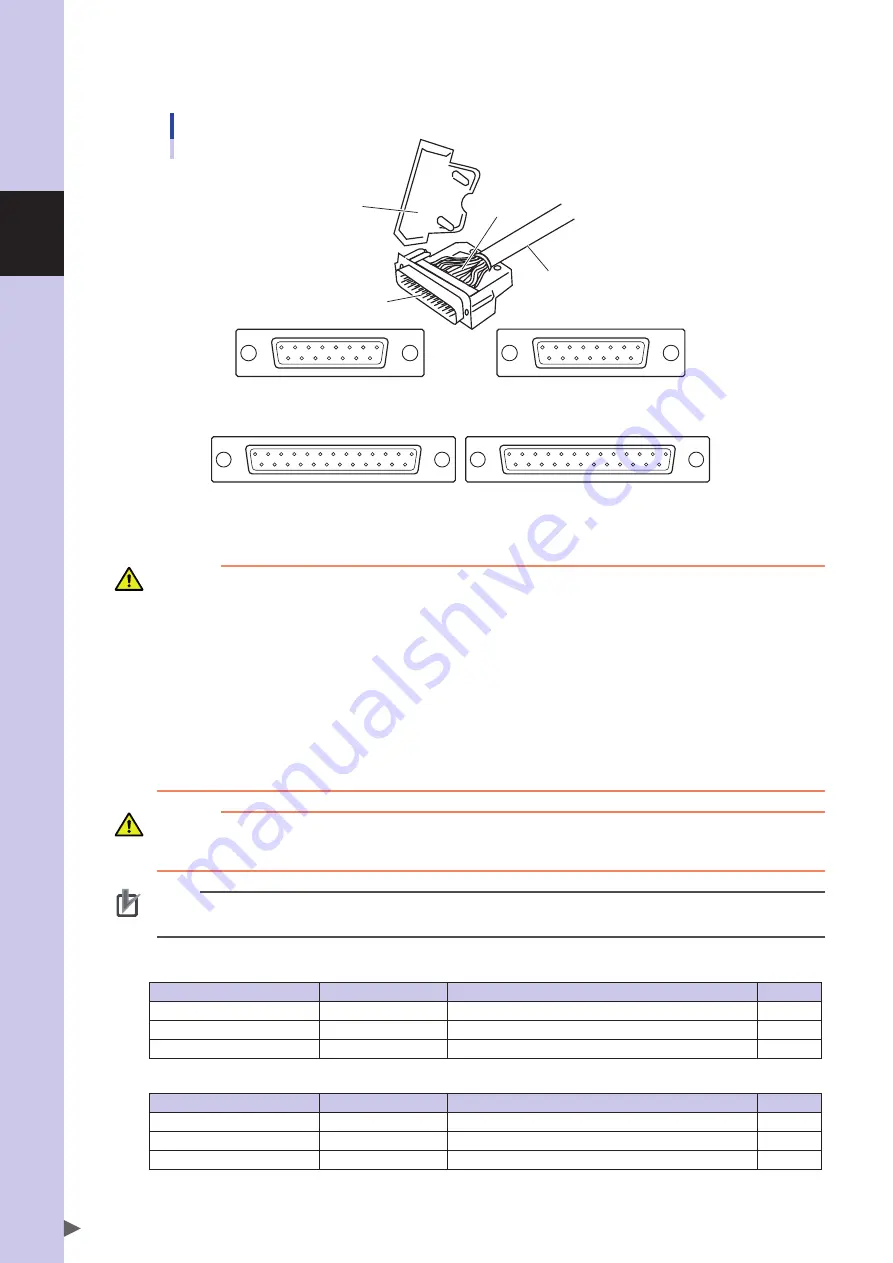
As shown in Fig. below, solder the user cable wires to the d-sub connector (supplied with the robot). Reattach the hood
to the D-sub connector after soldering, then plug it into the user wiring connector.
The connector pinouts as viewed from the solder side are shown below.
13 12 11 10 9 8 7 6 5 4
3 2 1
25 24 23 22 21 20 19 18 17 16 15 14
1
2 3 4
5 6 7 8 9 10 11 12 13
14 15 16 17 18 19 20 21 22 23 24 25
8 7 6 5 4
3 2 1
15 14 13 12 11 10 9
1 2 3 4 5
6 7 8
9 10 11 12 13 14 15
D-sub connector connections and pin assignments
Cable to be
prepared by user
Soldering
Hood
D-sub connector
D-sub connector on arm side
(As viewed from solder side)
D-sub connector on base side
(As viewed from solder side)
R6YXG500, R6YXG600, R6YXGH600, R6YXG700, R6YXG800, R6YXG900, R6YXG1000
R6YXGS500, R6YXGS600, R6YXGS700, R6YXGS800, R6YXGS900, R6YXGS1000
D-sub connector on arm side
(As viewed from solder side)
D-sub connector on base side
(As viewed from solder side)
R6YXGL250, R6YXGL350, R6YXGL400, R6YXGL500, R6YXGL600
WARNING
• THE USER CAbLE WIRES SHoULd HAvE A SHIELd WIRE. ConnECT IT To THE SAmE no. pIn In THE d-SUb
ConnECToR on THE RoboT SIdE, WHICH ALSo ConnECTS To THE SHIELd WIRE. IF THIS TASK IS omITTEd,
noISE mAY CAUSE mALFUnCTIon oF THE RoboT.
• SECURELY ATTACH THE d-SUb ConnECToR (SUppLIEd WITH THE RoboT) InTo THE d-SUb ConnECToR on THE
RoboT SIdE, bY TIGHTEnInG THE SCREWS on THE ConnECToR Hood. IF THIS ConnECToR ComES LooSE oR
ComES oFF, mALFUnCTIon mAY RESULT.
• mAKE SURE THAT THE USER CAbLE ATTACHEd To THE d-SUb ConnECToR FoR USER WIRInG And THE TUbE
ATTACHEd To THE bULKHEAd UnIon FoR USER TUbInG WILL noT InTERFERE WITH THE RoboT movEmEnT,
EnTAnGLE ARoUnd THE RoboT oR FLAp ARoUnd dURInG opERATIon. WIRInG And TUbInG mIGHT THEn bE
dAmAGEd CAUSInG mALFUnCTIon oF THE RoboT.
• LAY oUT THE USER CAbLE ATTACHEd To THE d-SUb ConnECToR FoR USER WIRInG And THE TUbE ATTACHEd
To THE bULKHEAd UnIon FoR USER TUbInG So THAT THEY do noT obSTRUCT THE movEmEnT oF THE
opERAToR oR AnY oTHER pERSonS. bodILY InJURY mAY RESULT IF AnYonE TRIpS on THE CAbLE oR AIR
TUbE.
CAUTION
• The d-sub connector supplied with the robot should be connected to the arm side by pin contact, and to the pedestal side by socket
contact. Use caution at these points when soldering.
• be sure to use the d-sub connector and hood which are supplied with the robot. Using other types may result in contact failure.
NOTE
Fasten user cable or tube newly with the machine harness while referring to "11. Installing the user wiring and tubing newly" in this
Chapter.
D-sub connectors (supplied with robot)
R6YXGL250, R6YXGL350, R6YXGL400, R6YXGL500, R6YXGL600, R6YXGS300, R6YXGS400
Part Name
OMRON Part No.
Part No.
Quantity
Base side D-sub connector
K58-m4872-101
dA-15S-nR (Japan Aviation Electronics Industry,Limited)
1
Arm side D-sub connector
K58-m4871-101
dA-15p-nR (Japan Aviation Electronics Industry,Limited)
1
Hood
K58-m4839-001
dA-C1-J10R (Japan Aviation Electronics Industry,Limited)
2
R6YXG500, R6YXG600, R6YXGH600, R6YXG700, R6YXG800, R6YXG900, R6YXG1000
R6YXGS500, R6YXGS600, R6YXGS700, R6YXGS800, R6YXGS900, R6YXGS1000
Part Name
OMRON Part No.
Part No.
Quantity
Base side D-sub connector
Kn0-m4872-002
db-25S-nR (Japan Aviation Electronics Industry,Limited)
1
Arm side D-sub connector
Kn0-m4871-002
db-25p-nR (Japan Aviation Electronics Industry,Limited)
1
Hood
Kn0-m4839-001
db-C2-J9R (Japan Aviation Electronics Industry,Limited)
2
To check the operation and signal transmission between the end effector and the controller or peripheral equipment after
making connections, refer to the section "4.5.1 Trial Operation" in Chapter “Safety Instructions” of this manual.
Summary of Contents for R6YXG500
Page 1: ...ZX T Series Cat No I155E EN 03A R6Y XG series INSTALLATION MANUAL SCARA Robots XG Series...
Page 2: ......
Page 10: ......
Page 36: ......
Page 38: ......
Page 40: ......
Page 46: ......
Page 48: ......
Page 56: ......
Page 174: ......
Page 176: ......
Page 220: ......
Page 221: ...Chapter 4 Periodic inspection Contents 1 Overview 4 1 2 List of inspection items 4 2...
Page 222: ......
Page 226: ......
Page 227: ...Chapter 5 Harmonic drive replacement period Contents 1 Overview 5 1 2 Replacement period 5 2...
Page 228: ......
Page 232: ......
Page 238: ......
Page 240: ......
Page 244: ......
Page 246: ......
Page 323: ...8 Specifications 8 77 1 3 Robot inner wiring diagram Robot inner wiring diagram R6YXG500...


