


3
Robot settings
3-17
■
Adjusting the R-axis machine reference
CAUTION
As the machine reference value is adjusted, the origin position may change. In this case, it is necessary to set the point data again after
the machine reference value has been adjusted.
Follow the steps below to adjust the R-axis machine reference value.
Prepare a wrench for a width across flat of 13 mm.
1
Turn on the controller.
Check that no one is inside the safety enclosure, and
then turn on the controller.
2
Perform the absolute reset.
Perform the absolute reset from outside the safety
enclosure.
For details about how to perform the absolute reset,
see "2.3 Absolute reset procedures".
3
Check the machine reference value.
If the machine reference value displayed on the
pbEX/pb is not in the range between 30 and 70
(recommended range) after the absolute reset has
been completed, follow the steps below to adjust the
machine reference value.
4
Place a sign indicating the robot is
being adjusted.
Place a sign indicating the robot is being adjusted, to
keep others from operating the controller or operation
panel.
5
Turn off the controller.
6
Enter the safety enclosure.
7
Put a mark at the origin position.
Scribe a mark at the current origin position on the
R-axis of the robot.
At this time, be careful to prevent the origin position
from deviating since the tip tool is touched.
8
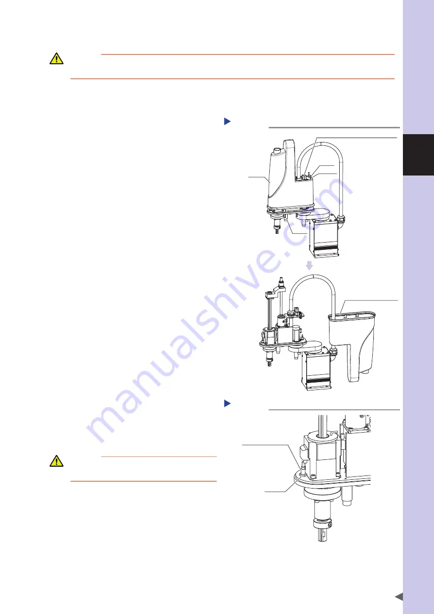
Remove the cover.
Remove the cover while referring to
"13. Detaching or attaching the covers" in Chapter 2.
Removing the cover
Step 8
Cover
Screw
Washer
Screw
Place the cover so that
it is not damaged.
Remove the D-sub connector hood.
9
Loosen the hex nut.
Using the wrench, loosen the hex nut that secures the
R-axis origin sensor.
Moving the R-axis origin sensor
Step 9-11
R-axis origin sensor
Hex nut
CAUTION
It is enough to loosen the nut. Do not remove the nut
completely.
Summary of Contents for R6YXG500
Page 1: ...ZX T Series Cat No I155E EN 03A R6Y XG series INSTALLATION MANUAL SCARA Robots XG Series...
Page 2: ......
Page 10: ......
Page 36: ......
Page 38: ......
Page 40: ......
Page 46: ......
Page 48: ......
Page 56: ......
Page 174: ......
Page 176: ......
Page 220: ......
Page 221: ...Chapter 4 Periodic inspection Contents 1 Overview 4 1 2 List of inspection items 4 2...
Page 222: ......
Page 226: ......
Page 227: ...Chapter 5 Harmonic drive replacement period Contents 1 Overview 5 1 2 Replacement period 5 2...
Page 228: ......
Page 232: ......
Page 238: ......
Page 240: ......
Page 244: ......
Page 246: ......
Page 323: ...8 Specifications 8 77 1 3 Robot inner wiring diagram Robot inner wiring diagram R6YXG500...


