


3
Robot settings
3-25
11
Move the Y-axis origin sensor stay.
Move the Y-axis origin sensor stay as follows.
As an approximate guide, a 0.8mm-movement equals
100%.
Y-axis machine reference value < 40%: move the
Y-axis origin sensor stay toward (a) shown in the
Fig.
Y-axis machine reference value > 60%: move the
Y-axis origin sensor stay toward (b) shown in the
Fig.
12
Secure the stay with the bolts.
Secure the X-axis origin sensor stay with the bolts.
13
Turn on the controller.
Check that no one is inside the safety enclosure, and
then turn on the controller.
14
Perform the absolute reset.
Perform the absolute reset from outside the safety
enclosure.
15
Check the machine reference value.
1. After the absolute reset has been completed, read
the machine reference value displayed on the
pbEX/pb.
2. If the machine reference value is in the range
between 40 and 60 (recommended range), then
the machine reference value has been completely
adjusted.
3. If it is outside the recommended range, then
repeat the procedure from step 4 again to readjust
it.
16
Turn off the controller.
17
Enter the safety enclosure.
18
Reattach the cover.
■
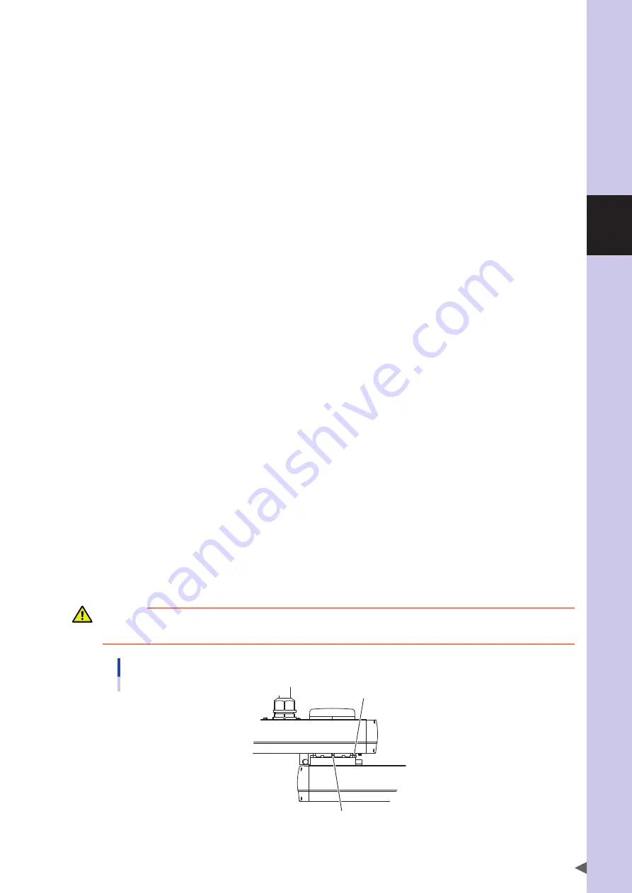
Changing the Y-axis origin position
The Y-axis origin position can be changed to any position in the range from the front position of the Y-axis arm and
X-axis arm to a maximum of 120° clockwise and counterclockwise at 30° intervals, by changing the positions of the
dog and the Y-axis speed reduction unit mounting bolt as shown below.
CAUTION
When the origin position has been changed, it is necessary to perform the absolute reset, adjust the machine reference value, and set the
standard coordinate and point data again.
Dog and Y-axis speed reduction unit mounting bolt
Dog
Y-axis speed reduction unit mounting bolt
Summary of Contents for R6YXG500
Page 1: ...ZX T Series Cat No I155E EN 03A R6Y XG series INSTALLATION MANUAL SCARA Robots XG Series...
Page 2: ......
Page 10: ......
Page 36: ......
Page 38: ......
Page 40: ......
Page 46: ......
Page 48: ......
Page 56: ......
Page 174: ......
Page 176: ......
Page 220: ......
Page 221: ...Chapter 4 Periodic inspection Contents 1 Overview 4 1 2 List of inspection items 4 2...
Page 222: ......
Page 226: ......
Page 227: ...Chapter 5 Harmonic drive replacement period Contents 1 Overview 5 1 2 Replacement period 5 2...
Page 228: ......
Page 232: ......
Page 238: ......
Page 240: ......
Page 244: ......
Page 246: ......
Page 323: ...8 Specifications 8 77 1 3 Robot inner wiring diagram Robot inner wiring diagram R6YXG500...


