


3
Robot settings
3-13
■
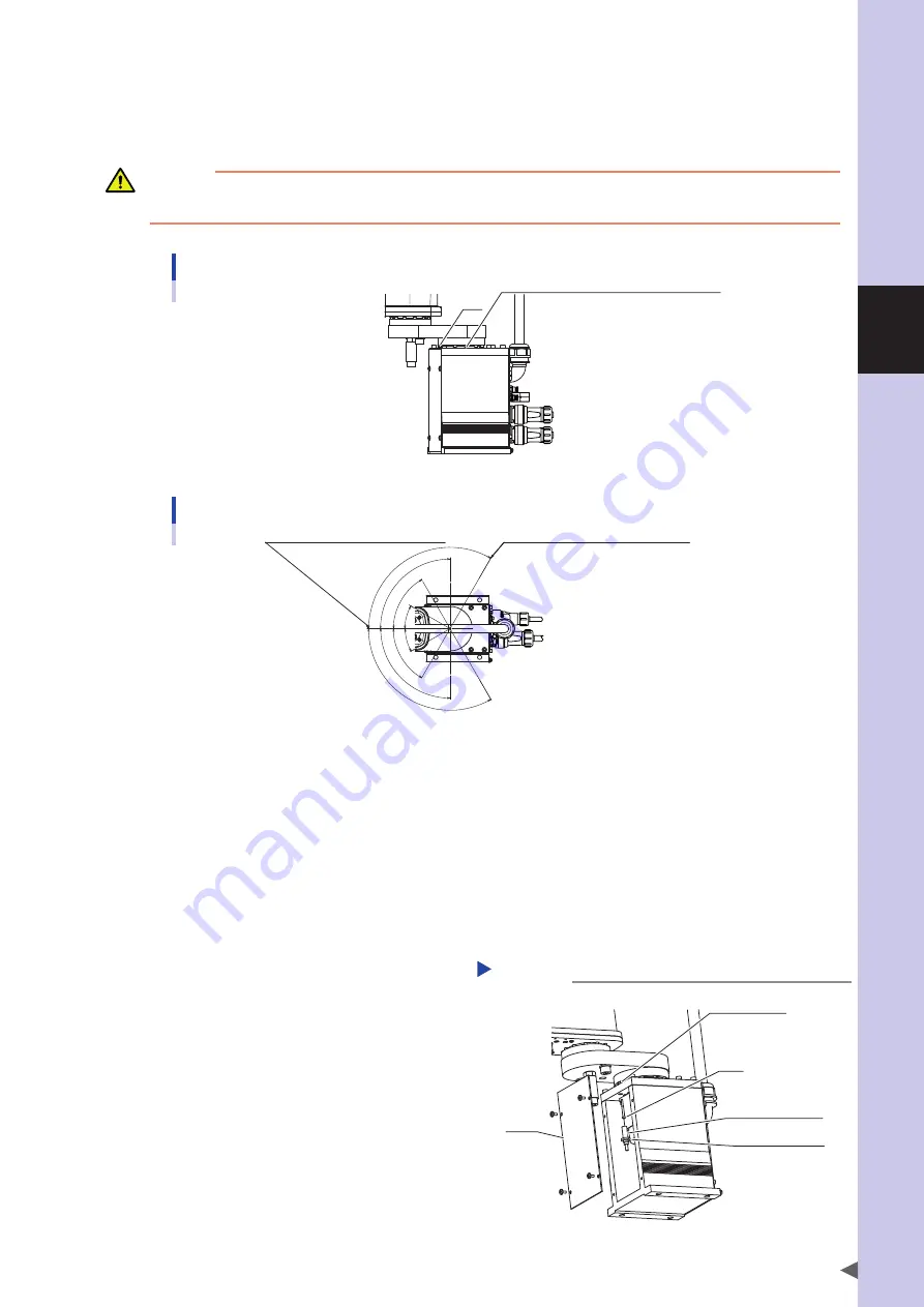
Changing the X-axis origin position
The X-axis origin position can be changed to any position in the range from the base front position of the X-axis to a
maximum of 120° clockwise and counterclockwise at 30° intervals, by changing the positions of the dog and the
mounting bolt for the X-axis speed reduction unit as shown below.
CAUTION
If the origin position has been changed, then the absolute reset must be performed, the machine reference must be adjusted, and the
standard coordinate and point data must be reset.
Dog and mounting bolt for X-axis speed reduction unit
Dog
Mounting bolt for X-axis speed reduction unit
X-axis origin position adjustable range
X-axis origin position adjustable range
Factory-preset X-axis origin position
120°
90°
60°
30°
30°
60°
90°
120°
The following describes how to change the X-axis origin position, for example, to a position 90° counterclockwise.
Prepare the tools listed below.
• Hex wrench set • Torque wrench • phillips screwdriver • Hex bit • phillips screwdriver bit
1
Turn on the controller.
Check that no one is inside the safety enclosure, and
then turn on the controller.
2
Perform the absolute reset.
Perform the absolute reset from outside the safety
enclosure.
For details about how to perform the absolute reset,
see "2.3 Absolute reset procedures".
3
Place a sign indicating that the robot
is being adjusted.
Place a sign indicating that the robot is being
adjusted, to keep others from operating the controller
or operation panel.
4
Turn off the controller.
5
Enter the safety enclosure.
6
Remove the cover.
Remove the cover while referring to
"13. Detaching or attaching the covers" in Chapter 2.
Removing the cover, connector,
X-axis origin sensor, and dog.
Step 6-9
Hex nut for dog
Dog
X-axis origin sensor
Hex nut for sensor
Cover
Summary of Contents for R6YXG500
Page 1: ...ZX T Series Cat No I155E EN 03A R6Y XG series INSTALLATION MANUAL SCARA Robots XG Series...
Page 2: ......
Page 10: ......
Page 36: ......
Page 38: ......
Page 40: ......
Page 46: ......
Page 48: ......
Page 56: ......
Page 174: ......
Page 176: ......
Page 220: ......
Page 221: ...Chapter 4 Periodic inspection Contents 1 Overview 4 1 2 List of inspection items 4 2...
Page 222: ......
Page 226: ......
Page 227: ...Chapter 5 Harmonic drive replacement period Contents 1 Overview 5 1 2 Replacement period 5 2...
Page 228: ......
Page 232: ......
Page 238: ......
Page 240: ......
Page 244: ......
Page 246: ......
Page 323: ...8 Specifications 8 77 1 3 Robot inner wiring diagram Robot inner wiring diagram R6YXG500...


