55
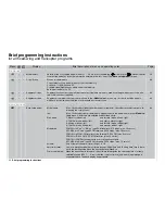
Brief programming instructions
which servos 9 and 10 take up the neutral position, and servos 1 … 8 take up the positions they
had at the time the
STO
fi eld was last operated.
“Battery F.S.”:
three possible servo positions can be selected (-75%, 0%, +75%) plus “off” for the servo connec-
ted to output 1 for fi xed-wing models and helicopters.
In SPCM20 mode:
Servos 1 … 8 can be programmed individually to hold-mode or position mode. Store position using
STO
. Servos 9
and 10 remain in hold mode.
148
In APCM24 mode:
Servos 1 … 12 can be programmed individually to hold-mode or position mode. Store position using
STO
.
149
•
•
Teacher/pupil
After assigning a switch (preferably the momentary switch SW8), control functions 1 … 10 can be transferred to a
Pupil transmitter. Since the model is basically controlled by the Teacher transmitter, all model programming is also
carried out at the Teacher transmitter. The control functions of the Pupil transmitter must act directly on the con-
trol channels, i. e. the receiver outputs, without the infl uence of any mixers or other settings. The modulation of
the Pupil transmitter must be set to PPM18 or PPM24, regardless of the settings at the Teacher transmitter. Stick
mode, throttle / collective pitch reverse and idle trim should be set up on the Pupil transmitter to suit the pupil’s
preferences.
150
•
•
Rx. output swap
Interchanging the receiver outputs. All the remaining coupling and mixer functions, servo adjustments etc. are un-
affected by this, i. e. they do not need to be changed if you alter the receiver output sequence.
Exception: Fail-Safe is always defi ned by the receiver sockets alone.
153
Global functions
Global functions
•
•
Basic settings
Owner’s name:
max. 15 characters (letters, numbers, special symbols). Use the rotary control to select
characters from the symbol table on the second screen page.
Preset stick mode:
the stick mode selected at this point is adopted as standard for all model memories, but
can be changed if desired.
Preset modulation:
PCM20 for all “mc” or “DS mc” type PCM receivers (512 steps)
SPCM20 for all “smc” type SPCM receivers (1024 steps)
PPM18 for all PPM-FM receivers to date except DS 24 FM
PPM24 for “DS 24 FM” PPM FM receiver
PPM10 for PPM-FM receivers with no more than fi ve servo outputs
APCM24 for all “amc” type APCM receivers (1024 steps)
Preset min. pitch:
defi nes the collective pitch minimum position of the C1 stick – “forward” or “back”.
Display light:
sets the duration of the screen backlighting. The options are 30, 60, 120 seconds or “un-
limited”.
Power-on beep:
switches the
mx
-24s identifi cation melody on and off
154
Display
Menu
Brief description of menu and operating notes
Page
Summary of Contents for mx-24s
Page 1: ...1...
Page 19: ...19 For your notes...
Page 35: ...35 For your notes...
Page 41: ...41 41 For your notes...
Page 57: ...57 For your notes...
Page 63: ...63 63 For your notes...
Page 69: ...69 69 For your notes...
Page 85: ...85 85 For your notes...
Page 99: ...99 For your notes...
Page 143: ...143 For your notes...
Page 191: ...191 For your notes...
Page 212: ...212 212 For your notes...
Page 213: ...213 213 For your notes...
Page 214: ...214 For your notes...
Page 216: ...216...


