119
up-fl ap.
+100%
0%
0%
0%
0%
0% 0% 0%
0%
0%
0% +100%+100%
0% 0% 0%
0%
SYM
+100%
0%
+100%+100%
0%
0%
0%
ASY
SYM
ASY
SYM
ASY
FL2
AILE
FLAP
AI
Ail–tr
Diff.
Fl.pos
FL
El–>Fl
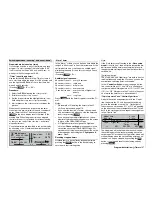
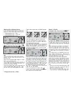
Select
SYM
in order to set symmetrical travels for up-
and down-elevator, or
ASY
for different travels either
side of neutral.
The available range of values is -150% to +150%,
while pressing
CLEAR
resets the value to 0%.
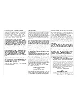
Important general note:
It is essential to ensure that the control sur-
faces and servos do not strike their mechani-
cal end-stops (stalled servos) when large travels
are set. This is a particular danger with the com-
bined functions “
Al
” and “
FL
”. We recom-
mend that you make use of the “Travel limit” op-
tion which is available in the »Servo adjustment«
menu (see page 74).
Brake settings
The “Brake settings” menu is switched “off” if you en-
tered “Motor on C1 forward / back” in the »
Model
type
« menu (see page 70), and leave “yes” for the
currently active fl ight phase in the “Motor” column of
the »
Phase settings
« menu (see page 100). You may
therefore need to switch fl ight phases.
Please note that all the “Brake mixers” described in
the following section are global in nature, i. e. they ap-
ply equally to all fl ight phases, and cannot be altered
for specifi c phases of fl ight. This means that the effect
of the brake settings can only be set up optimally to
suit one particular fl ight phase.
Landing time can be nerve-racking, and to ensu-
119
Program description:
Mixers
re that you have set the “optimum” fl ight phase when
the brake system is activated, the software provides
a form of automation. You will fi nd an example of this
later, in the section entitled “Using fl ight phases” on
page 174.
Crow
AILE
FLAP
FL2
Crow
0%
0%
Diff. reduct.
0%
0%
0%
Elevat. curve
0%
=>
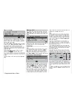
B R A K E S E T T I N G S
The mixer functions “Brake
AILE, FLAP and – if
present – FL2” are actuated by control function 1, 7, 8
or 9, depending on which input you have assigned to
the “Brake” function in the »
Model type
« menu (see
page 70).
Note:
In the »
Model type
« menu (see page 70) you should
also defi ne the offset, i. e. the direction of operati-
on. We suggest that you position the offset at about
+90% of stick travel (if the C1 stick is used, this is ge-
nerally located at the forward position of the stick). To
extend the brakes the stick must therefore be moved
back towards the pilot. The remainder of the stick tra-
vel of around 10% then has no effect. However, it is
not “wasted”, as the control travel is automatically ex-
panded to 100% by the software.
Use the select fi elds
AILE
,
FLAP
and – if present –
FL2
to defi ne the extent and direction to which the
corresponding pairs of fl aps are to follow when the
airbrake control (control function 1, 7, 8 or 9) is opera-
ted. If the model does not feature separate (conventi-
onal) airbrakes, leave the corresponding receiver out-
put free.
The available range of values is -150% to +150%,
while pressing
CLEAR
resets the value to 0%.
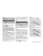
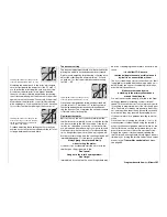
a) AILE settings
When the model is braked on the landing ap-
proach, both pairs of ailerons should never de-
fl ect up by more than about half of their full travel,
otherwise there will not be suffi cient aileron throw
available to provide roll control on the approach.
AILE
FLAP
FL2
FL2
FLAP
AILE
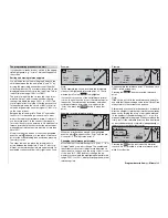
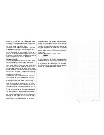
b) FLAP and FL2 settings
When the model is braked on the landing ap-
proach, both pairs of fl aps can be set to defl ect by
different amounts, e. g.:
AILE
FLAP
FL2
FL2
FLAP
AILE
AILE
FLAP
FL2
FL2
FLAP
AILE
Summary of Contents for mx-24s
Page 1: ...1...
Page 19: ...19 For your notes...
Page 35: ...35 For your notes...
Page 41: ...41 41 For your notes...
Page 57: ...57 For your notes...
Page 63: ...63 63 For your notes...
Page 69: ...69 69 For your notes...
Page 85: ...85 85 For your notes...
Page 99: ...99 For your notes...
Page 143: ...143 For your notes...
Page 191: ...191 For your notes...
Page 212: ...212 212 For your notes...
Page 213: ...213 213 For your notes...
Page 214: ...214 For your notes...
Page 216: ...216...


