166
Programming examples: Fixed-wing model
Example 1
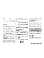
Using the right or left side-mounted proportional
control 9 or 10
At the receiver end you require a proportional speed
controller.
With these transmitter controls it is a very simple mat-
ter to include the power system in the programming.
All you have to do is assign one of the two controls
in the »
Transmitter control adjust
« menu, and con-
nect the controller to the corresponding servo output
socket on the receiver – in this example, Output “9”.
Either of these two proportional controls can be used
to provide fully proportional control of motor speed.
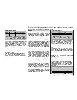
For example, assign the left-hand proportional control
CONTROL 10
to the fl ight phase independent
input 9
in the menu …
»Control adjust« (page 78)
0%
+
100%+100% 0.0 0.0
0% +100%+100% 0.0 0.0
0% +100%+100% 0.0 0.0
0% +100%+100% 0.0 0.0
SYM ASY
ASY
SYM
SEL
SEL
«normal »
Cnt. 10
12
11
10
9
–time+
Input
Input
Input
Input
free
free
free
–
offset
… and, if necessary, adjust the travels to suit your
speed controller.
Pressing the
HELP
button with the rotary control
pressed in now takes you to the »
Servo display
«.
Move the transmitter control, and you will see the bar
for Channel 9 move from one side to the other and
back.
However, if you later move the proportional control
forward too quickly when you are at the fl ying fi eld,
you may fi nd that the abrupt motor start places an ex-
tremely severe load on the whole power train; you
should certainly take measures to avoid this problem.
Use the rotary control to activate the
ASY
mmetri-
Example 2
Using one of the two three-position switches
(CTRL 7 or 8)
This variant implements a multi-stage switching sys-
tem for the drive motor using the OFF – half-throttle –
full throttle method. At the receiver end you require a
proportional speed controller.
In principle the settings required for this are the same
as described for Example 1, and the same remarks
and recommendations apply.
Apart from the proportional speed control provided by
Example 1 and the three-stage speed control provi-
ded by Example 2, the choice of one of the two types
of transmitter controls only affects the type of timer
control; see page 170.
Note:
It is possible to adjust the “half-throttle setting” by shif-
ting the neutral point and then adjusting the travel: de-
duct the offset value from the travel on the side whe-
re the neutral point was shifted, and add the same va-
lue on the other side, i. e. for an offset value of -20%:
+80% on the minus side of travel and +120% on the
plus side, and vice versa with an offset of +20%.
Example 3
Using a two-position switch SW 1 … 4 or 7
This variant implements a pure ON / OFF function.
At the receiver end you would use either a simple
electronic switch, or – if you prefer a “soft” motor start
– a proportional speed controller.
The settings required for this are basically the same
as those described for Example 1. The same remarks
and recommendations apply.
In this case the only difference from the earlier de-
scription is the way the selected switch is displayed in
the following menu:
cal value input below the “-time+” column, and then
move the selected control to the “ON” position, so that
the highlighted fi eld “changes sides”. Enter a value
of at least one second, so that the motor starts more
smoothly if you move the proportional control too
quickly in the direction of “ON”. Now switch back to
the »
Servo display
« and reassure yourself that the
system works as expected.
0%
+
100%+100%
0% +100%+100% 0.0 0.0
0% +100%+100% 0.0 0.0
0% +100%+100% 0.0 0.0
SYM ASY
ASY
SYM
SEL
SEL
«normal »
0.0
1.0
12
11
10
9
–time+
Cnt. 10
Input
Input
Input
Input
free
free
free
–
offset
Note:
It is important that you can switch the motor off in-
stantly at any time, so do not enter a time delay on
the “OFF” side. This does not place an excessive load
on the power train, as the motor simply “runs down”
naturally.
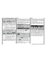
The control travels and direction for the speed cont-
roller are usually adjusted in the “-” column of
the »
Transmitter control adjust
« menu. Alternatively
you can enter these settings in the menu …
»Servo adjustment« (page 74)
Servo 6
=>
0% 100% 100% 150% 150%
Servo 7 =>
0% 100% 100%
150% 150%
Servo 8 =>
0% 100% 100%
150% 150%
Servo 9 =>
0% 100% 100%
150% 150%
SEL
SYM ASY
SYM ASY
SEL
Rev cent. – travel
+
– limit +
Summary of Contents for mx-24s
Page 1: ...1...
Page 19: ...19 For your notes...
Page 35: ...35 For your notes...
Page 41: ...41 41 For your notes...
Page 57: ...57 For your notes...
Page 63: ...63 63 For your notes...
Page 69: ...69 69 For your notes...
Page 85: ...85 85 For your notes...
Page 99: ...99 For your notes...
Page 143: ...143 For your notes...
Page 191: ...191 For your notes...
Page 212: ...212 212 For your notes...
Page 213: ...213 213 For your notes...
Page 214: ...214 For your notes...
Page 216: ...216...


