100
Program description:
Flight phases
Phase settings
Setting up fl ight phases
The
mx
-24s enables you to program up to eight
groups of settings within any one model memory; the
settings typically differ from each other in order to ca-
ter for different stages of a fl ight. The grouped set-
tings are termed fl ight phases, and are programmed
in the corresponding menus.
Depending on the setting “Throttle min. forward /
back” or “none” in the “Motor on C1” line of the »
Mo-
del type
« menu …
M O D E L T Y P E
Tail type
Aileron/camber flaps
Brake
SEL
Offset
+100%
Input 1
Normal
1 AIL
Motor on C1
None
… your transmitter’s screen will show one of the follo-
wing two variants:
• Motor on C1 “none”
Phase 1
Phase 2
0.1s
Phase 3
0.1s
-
Phase 4
Name
SEL
SEL
normal
0.1s
Thermik
Fl.ph.Tim
Sw. time
0.1s
SEL
-
-
• Motor on C1 “Throttle min. forward / back”
Phase 1
Phase 2
0.1s
Phase 3
0.1s
-
Phase 4
Name
SEL
SEL
normal
0.1s
Thermik
Timer
Sw. time
0.1s
SEL
-
-
SEL
Motor
yes
yes
yes
yes
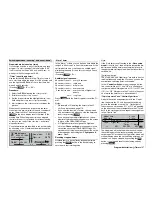
Setting up fl ight phases
When setting up fl ight phases for fi xed-wing models
you start in this menu point, where individual phases
are assigned names, and transition times can be set
to provide a smooth transition from one phase
into
the next. In practice we have certainly found that tran-
sition times longer than the default 0.1 second are
desirable, but the optimum setting varies according
to your model and its set-up. You can assign names
and transition times to multiple phases at this stage
even if you don’t intend to make use of them at pre-
sent, because you do not decide which of the “occu-
pied” phases will actually be activated until you move
to the »
Phase assignment
« menu, as described on
page 104.
The right-hand “Status” column shows whether swit-
ches have already been assigned to the phases 1 …
8, and what the current status of the switches is:
Symbol
Meaning
–
No switch assigned
+
Phase can be called up by switch
Indicates the currently active phase
number
Note:
A useful aid when programming different fl ight phases
is the “Copy fl ight phase” option, which you will fi nd in
the »
Copy / Erase
« menu. The fi rst step is to estab-
lish the parameters for a particular fl ight phase; you
then copy these settings into the next fl ight phase,
where they can be modifi ed to meet the requirements
of the new stage of fl ight.
“Name” column
Press the rotary control and select the most suitab-
le phase name for phases 1 to 8 (if required for your
particular model) from the on-screen list. In additi-
on to these standard names you can defi ne a maxi-
mum of ten of your own phase names in the »
Gene-
ral basic settings
« menu (see page 154).
The sequence of phases 1 to 8 is of no signifi cance;
you do not even have to make the numbers concur-
rent. However, you should always start with “Phase
1”, as this is the “Normal phase”, which is always ac-
tive if:
• no phase switch has been programmed in the
»
Phase assignment
« menu, and
• no phase has been assigned to particular switch
combinations.
The phase name “normal” would therefore be a sen-
sible choice for “Phase 1”. The names themselves
have absolutely no technical signifi cance in terms
of programming; their only purpose is to help you to
identify them in the course of further programming,
and to know which fl ight phase is switched on at any
one time. For this reason the names are shown in all
the fl ight phase specifi c menus, and are also included
in the transmitter’s basic display.
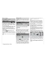
“Flight phase timer” and “Timer” column
In addition to the standard timers in the basic screen
display, further timers are available which can be set
up in the “Flight phase timers” menu (see page 108).
Timer select list:
Clk 1, Clk 2, Clk 3, Lap, Time1, Time2.
The fl ight phase timers “Clk 1 … 3” and “Time1” and
“Time2” only run in the fl ight phase to which they
have been assigned in this menu. In other fl ight pha-
ses they are stopped (and suppressed), and the start
/ stop switches assigned to them have no effect.
In contrast, the lap-counter continues to run once
started, even if you switch to a different fl ight pha-
se, although it can be stopped from any fl ight phase
using the
ESC
button.
Obviously you can record lap times with “Lap” using
a switch (SW), but the meaning of the two timers
“Time1” and “Time2” is as follows:
Time1
This timer only records times for which a
switch, control switch or logical switch assi-
gned in the “Lap time / Tim tab” line of the
»
Flight phase timers
« menu is “closed” (see
page 108). The basic display shows the num-
Summary of Contents for mx-24s
Page 1: ...1...
Page 19: ...19 For your notes...
Page 35: ...35 For your notes...
Page 41: ...41 41 For your notes...
Page 57: ...57 For your notes...
Page 63: ...63 63 For your notes...
Page 69: ...69 69 For your notes...
Page 85: ...85 85 For your notes...
Page 99: ...99 For your notes...
Page 143: ...143 For your notes...
Page 191: ...191 For your notes...
Page 212: ...212 212 For your notes...
Page 213: ...213 213 For your notes...
Page 214: ...214 For your notes...
Page 216: ...216...


