173
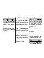
Two rudder servos
In this example we will connect two rudders “in paral-
lel”. The second rudder could be connected to recei-
ver output 8, which is not already in use.
Variant 1
Move to the menu ...
»Dual mixers« (page 144)
… and select one of the dual mixers. Enter “8” and
“RU” using
SEL
, as shown in this screen-shot:
8
0%
Diff.
SEL
? ?
? ?
0%
SEL
? ?
? ?
0%
SEL
RU
D U A L M I X E R
Mixer
Mixer
Mixer
1
2
3
Of course, the same-sense link “
”, which would
be available via “input 8”, must be disabled for this ap-
plication. For this reason it really is essential that you
set input 8 to “free” in the menu ...
»Control adjust« (page 78)
0%
+
100%+100% 0.0 0.0
0% +100%+100% 0.0 0.0
0% +100%+100% 0.0 0.0
0% +100%+100% 0.0 0.0
SYM ASY
ASY
SYM
SEL
SEL
«normal »
offset
–time+
libre
free
Input 5
free
Input 6
Input 7
Input 8
free
free
–
… in order to separate the control function from the
control channel.
If all the dual mixers are already in use for other pur-
poses, you can still fall back on the following alterna-
tive.
Variant 2
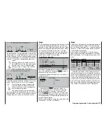
In this variant you move to the menu …
»Free mixers« (page 135)
8
=>
??
- - - -
??
??
- - - -
??
??
- - - -
SEL
SEL
SEL
RU
??
Tr
1
2
3
4
LinearMIX
type
LinearMIX
LinearMIX
LinearMIX
from
to
Adjust
… and set up a “Tr RU
8” mixer.
In the “Type” column select the “Tr” setting, to ensure
that the rudder trim affects both rudder servos.
Now switch to the graphic page and set a
SYM
metri-
cal mixer input of +100%:
+100%
+100%
0 %
m
OU
T
P
U
T
--
+
100
STO
ASY
SYM
CLR
8
RU
O f f s e t
Linear MIX 1
Mix input
Here again, “Input 8” should be programmed to “free”
in the »
Transmitter control adjust
« menu, in all
fl ight phases if you have set them up. It is easier to
separate control function (8) from control channel “8”
in the
fl ight phase independent
menu …
»MIX-only channel« (page 142)
1 2 3
5 6 7 8 9
1112
4
10
M I X O N L Y C H A N N E L
MIXonly
normal
173
Programming examples: Fixed-wing model
Two elevator servos
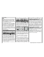
This time we need to wire up two elevator servos “in
parallel”. In accordance with the receiver socket se-
quence – see the section starting on page 37 – the
second elevator servo should be connected to recei-
ver output 8.
The software is pre-confi gured for this arrangement,
i. e. a suitable mixer is provided as standard. You will
fi nd this in the menu:
»Model type« (page 70)
In this menu hold the rotary control pressed in and
switch to the “Tail type” line, where you simply select
the “2 EL Sv 3+8” entry:
SEL
Offset
+100%
2 AIL
4 WK
2 EL Sv 3+8
M O D E L T Y P E
Tail type
Aileron/camber flaps
Brake
Input 1
Motor on C1
None
The travels of the two servos can be fi ne-tuned in the
familiar way using the »Two rudder servos
Servo ad-
justment
« menu.
Summary of Contents for mx-24s
Page 1: ...1...
Page 19: ...19 For your notes...
Page 35: ...35 For your notes...
Page 41: ...41 41 For your notes...
Page 57: ...57 For your notes...
Page 63: ...63 63 For your notes...
Page 69: ...69 69 For your notes...
Page 85: ...85 85 For your notes...
Page 99: ...99 For your notes...
Page 143: ...143 For your notes...
Page 191: ...191 For your notes...
Page 212: ...212 212 For your notes...
Page 213: ...213 213 For your notes...
Page 214: ...214 For your notes...
Page 216: ...216...


