110
What is a mixer?
Basic function
Wing mixers
Setting up the wing fl ap system
Program description:
Mixers
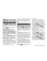
In many models it is often desirable to use a mixer to
couple various control systems, e. g. to link the aile-
rons and rudder, or inter-connect two servos where
two control surfaces are actuated by separate servos.
In all these cases the signal which fl ows directly from
a transmitter stick to the associated servo (the “out-
put” – i. e. at the control function input: see sketch) is
“bled off” at a particular point, and the derived signal
is then processed in a defi ned way so that it affects
another receiver output.
Example: controlling two elevator servos from the
elevator stick:
The
mx
-24s transmitter software contains a lar-
ge number of pre-programmed coupling functions as
standard, which are designed to mix together two (or
more) control channels. In our initial example the mi-
xer required is supplied “ready-made”, and just has
to be activated in the software by accessing the “Tail”
line of the »
Model type
« menu, where you would se-
lect “2 EL Sv 3+8”.
In addition to these pre-programmed mixers the soft-
ware also includes eight freely programmable line-
ar mixers, four curve mixers and four dual mixers (see
below) in the fi xed-wing and helicopter programs, all
of which can be used in each of the forty model me-
mories.
For more information please refer to the general no-
tes on “free mixers” in this manual, in the section star-
ting on page 134.
3
3
8
Se
rv
o
4,
8
V
C5
7
7
Be
s
t.
-N
r.
4
1
0
1
Se
rv
o
4,
8
V
C5
7
7
Be
s
t.
-N
r.
4
1
0
1
Transmitter
control
Control function
input
Control channel
(receiver output)
Mixer
Servo 1
Servo 2
W I N G M I X E R S
Multi-flap menu
Brake settings
Aileron
Flaps
«Normal »
=>
=>
2–>4 rudder
0%
6–>3 elevator
0%
0%
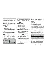
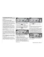
The sub-menus and options available in the fi xed-
wing menu structure vary solely according to the
number of aileron and fl ap servos which you have en-
tered in the »
Model type
« menu (see page 70), i. e.
the list only contains those set-up options which are
possible for your model confi guration. This helps to
keep the menu easy to understand, and also avoids
potential programming errors.
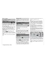
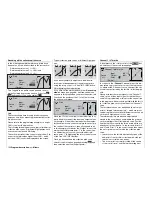
For example, if you set “2 AIL” (without fl aps), the dis-
play changes from that shown above to this one:
«Normal »
Brake settings
Aileron
Elevator
=>
2–>4 rudder
0%
3–>5 aileron
0%
0%
Aileron differential
0%
W I N G M I X E R S
Apart from the options grouped together under “Bra-
ke settings”, all the options can be programmed se-
parately for each fl ight phase. If you have set up mul-
tiple fl ight phases in the »
Phase settings
« (see page
100) and »
Phase assignment
« (see page 104) me-
nus, and have assigned names to them, the name of
the current fl ight phase will be displayed at the bottom
of the screen, e.g. “normal”.
Tips:
• The transmitter control for the airbrake mixers can
be re-programmed in the »
Model type
« menu
(see page 70) from channel 1 to channel 7, 8 or
9. The offset can also be determined at the same
point.
•
Note that a transmitter control assigned to in-
put 7 in the »Transmitter control adjust« menu
will be de-coupled by the software if two cam-
ber-changing fl aps are defi ned; this is inten-
ded to eliminate the danger of errors and mal-
functions.
The same applies to inputs 7 and 10 if you se-
lect “2 AIL 4 FL”.
•
If you wish to set up a Butterfl y (Crow) braking
system, with the ailerons raised and the fl aps (if
present) lowered, move to the “Brake settings”
sub-menu and enter the appropriate settings in the
“Crow” line.
•
If you wish to use the C1 stick to control both an
electric motor and a Butterfl y (Crow) system, you
should use the facilities provided in the »
Phase
settings
« menu; see the example on page 167.
•
We also suggest that you use the opportuni-
ty to set up
switch times
for a “smooth” change-
over from one fl ight phase to the next. This option
is available in the »
Phase settings
« menu (see
page 100).
•
If your model features multiple wing fl aps and a
“Crow / Butterfl y system” (see below), but without
(conventional) airbrakes, then Output 1, which
is generally free, can be separated from cont-
rol function 1 (throttle / brake stick) in the »
MIX
only channel
« menu (see page 142), and used
for another purpose with the help of a “free mixer”
(see page 135).
•
If you simply select “2AIL” in the »
Model type
«
menu (see page 70), the fl ight phase specifi c fl ap
function for the ailerons can be obtained by ente-
ring a suitable offset for Input 5 in the »
Transmit-
ter control adjust
« menu (see page 78).
• We recommend that you make use of the Servo
Display facility, where you can directly check the
results of your settings. This is available from virtu-
ally any menu position by pressing the
HELP
but-
ton with the rotary control pressed in.
Summary of Contents for mx-24s
Page 1: ...1...
Page 19: ...19 For your notes...
Page 35: ...35 For your notes...
Page 41: ...41 41 For your notes...
Page 57: ...57 For your notes...
Page 63: ...63 63 For your notes...
Page 69: ...69 69 For your notes...
Page 85: ...85 85 For your notes...
Page 99: ...99 For your notes...
Page 143: ...143 For your notes...
Page 191: ...191 For your notes...
Page 212: ...212 212 For your notes...
Page 213: ...213 213 For your notes...
Page 214: ...214 For your notes...
Page 216: ...216...


